
Automatic reducing pore-forming device mounted on drilling machine

A hole former and automatic technology, applied in drill bits, drilling equipment, earthwork drilling and other directions, can solve the problems of large friction resistance between the hole former and the soil, increased consumption of oil and other materials, and high equipment purchase costs, and achieve higher The effect of labor productivity, consumption reduction, and purchase cost savings

Inactive Publication Date: 2014-05-07
赵小勇
View PDF5 Cites 3 Cited by
  • Summary
  • Abstract
  • Description
  • Claims
  • Application Information

AI Technical Summary

Problems solved by technology

[0002] The bottom of the current hole former is conical. During the hole forming process by non-rotary drilling methods such as driving in or pressing in, the soil around the hole former is squeezed. When the hole former is lifted, the hole former and the soil The friction resistance between them is very large, and a large pulling force is often required to lift the hole forming device out of the hole. The power of the equipment that needs to be lifted is often large, and the equipment purchase cost is relatively high, and the consumption of oil and other materials during the construction process will also be greatly increased. increase, so that the overall construction cost is relatively high
At the same time, there are many unsafe factors in too large pulling force.

Method used


Image

  • Automatic reducing pore-forming device mounted on drilling machine
  • Automatic reducing pore-forming device mounted on drilling machine
  • Automatic reducing pore-forming device mounted on drilling machine

Examples


Embodiment Construction

[0021] The present invention will be further described in detail below in conjunction with the accompanying drawings and specific embodiments.

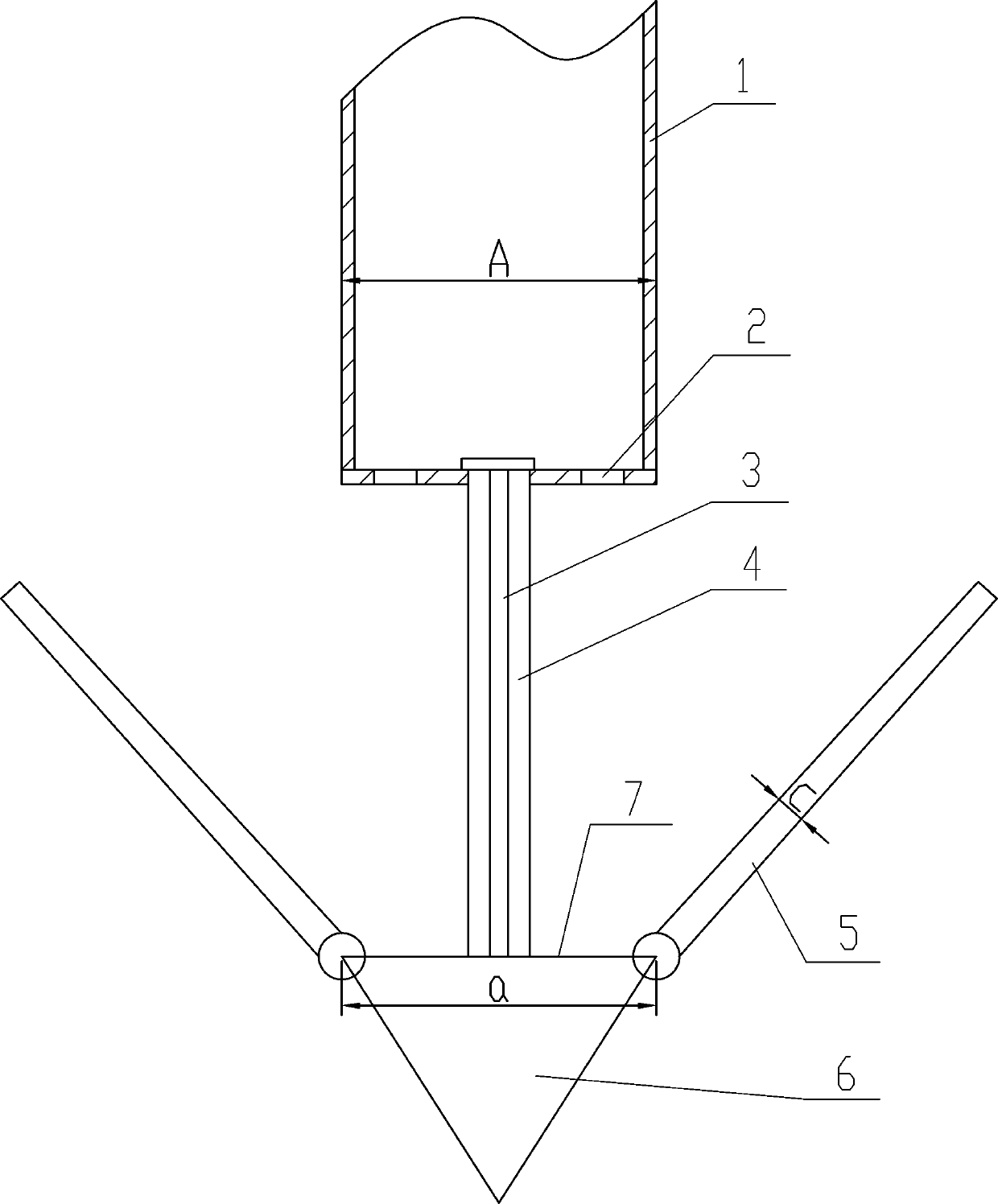
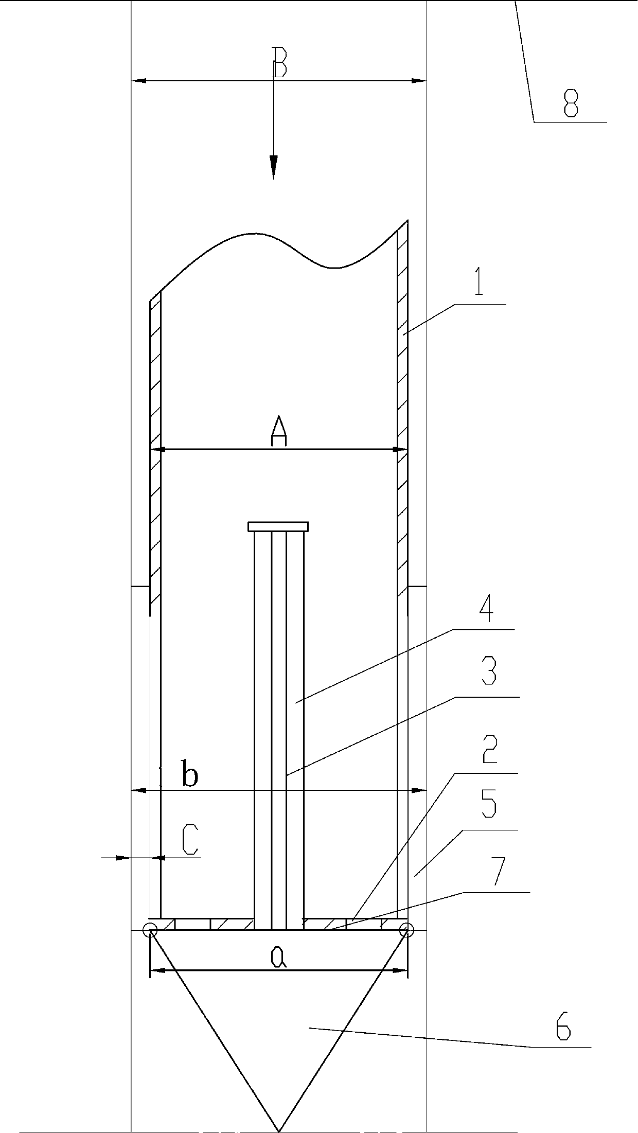
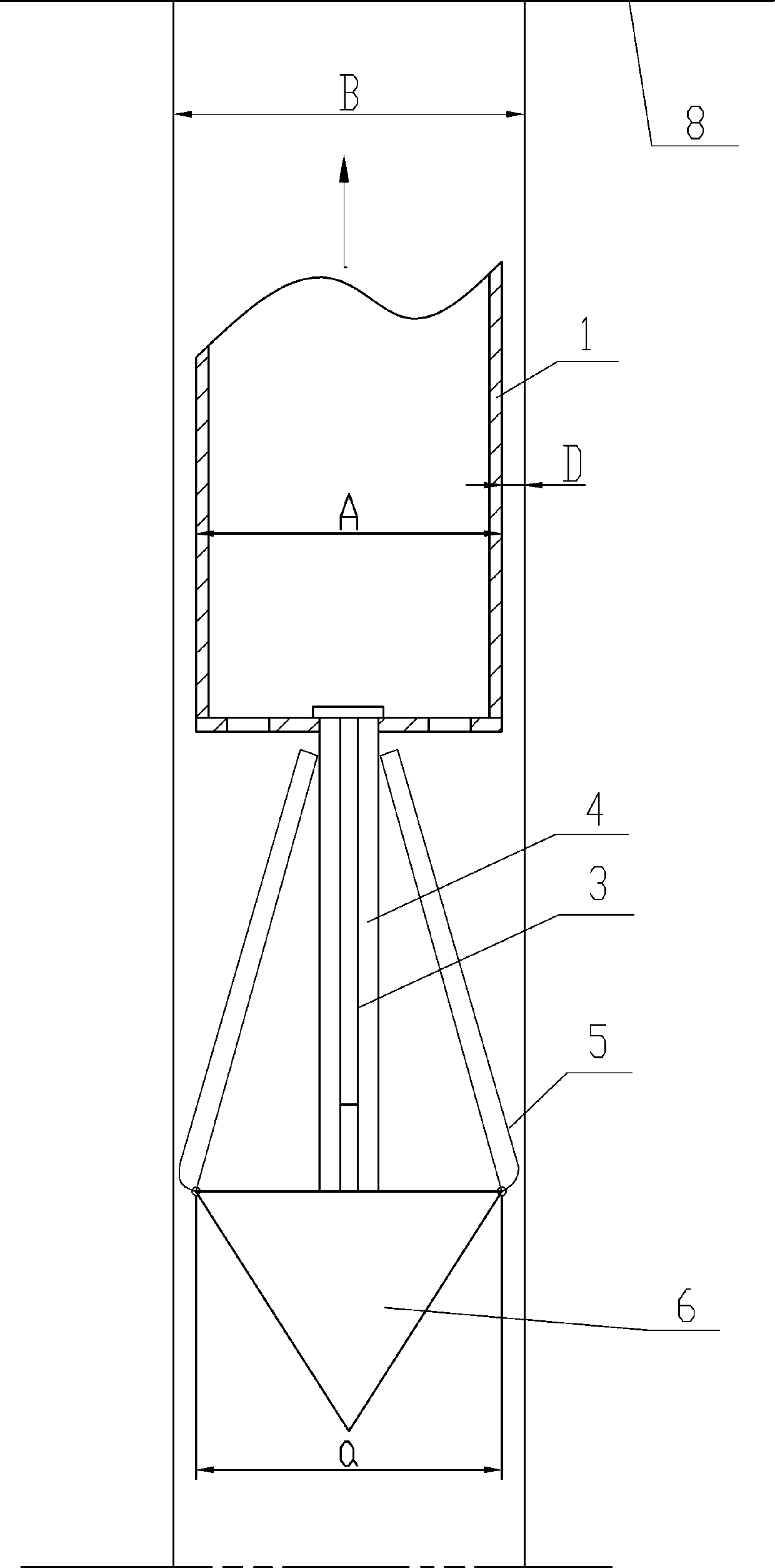
[0022] See attached figure 1 , the present invention comprises a pile pipe 1, a guide rod 4, a flap 5 and an inverted cone pile tip 6, the guide rod 4 is movably connected to the bottom of the pile pipe 1, and the lower end of the guide rod 4 is fixedly connected to the pile tip 6 3-6 flaps 5 are hinged on the edge of the upper end surface 7 of the pile point 6, and the flaps 5 are arranged side by side. When the hole is opened, the flaps 5 are closed and hold the pile pipe 1 tightly. After closing, there is a distance of 5-6 cm between two adjacent flaps 5, and a slender iron sheet or iron plate is welded on the pile pipe 1. (Its shape is also an arc matching the outer wall of the pile pipe 1). The iron sheet is located in the gap between the two flaps 5, and its length is basically the same as that of the flap 5; the diameter a of ...


PUM


Abstract

The invention discloses an automatic reducing pore-forming device mounted on a drilling machine. The automatic reducing pore-forming device comprises a pile pipe, a guide rod, movable boards and an inverted conical pile tip, the guide rod is movably connected to the lower portion of the pile pipe, the lower end of the guide rod is fixedly connected with the pile tip, 3-6 movable boards are hinged to the edge of the upper end face of the pile tip and arranged side by side, a 5-6cm distance is reserved between every two adjacent movable boards, the movable boards are arc-shaped and are closed and tightly hold the pile pipe when pores are formed, and the diameter a of the upper end face of the pile tip is not larger than the diameter A of the pile pipe. The automatic reducing pore-forming device is simple, convenient to operate, low in lifting resistance and high in pore-forming speed, and labor productivity is greatly improved. The pore-forming process can be widely applied to construction of foundations such as civil and industrial building foundations, railways, roads, bridges and harbors.

Description

technical field [0001] The invention relates to an automatic variable-diameter hole forming device installed on a drilling machine. Background technique [0002] The bottom of the current hole former is conical. During the hole forming process by non-rotary drilling methods such as driving in or pressing in, the soil around the hole former is squeezed. When the hole former is lifted, the hole former and the soil The friction resistance between them is very large, and it often requires a large pulling force to lift the hole forming device out of the hole. The power of the equipment that needs to be lifted is often large, and the equipment purchase cost is relatively high, and the consumption of oil and other materials during the construction process will also be greatly increased. increase, so that the overall construction cost is relatively high. There are also many unsafe factors in too large a pulling force simultaneously. Contents of the invention [0003] The technic...

Claims


Application Information

Patent Timeline
Patent Type & Authority Applications(China)
IPC IPC(8): E21B10/62
Inventor 付永社张志田赵小勇郝国利赵璞宋立恩刘彦林孟巍
Owner 赵小勇
Learn More