
Hydraulic system for tunnel loading test platform

A loading test, hydraulic system technology, applied in the direction of fluid pressure actuation device, servo motor, mechanical equipment, etc., can solve problems such as single means, and achieve the effect of reducing control components, rational design and application, and reliable and safe use

Inactive Publication Date: 2014-05-07
BEIJING JIAOTONG UNIV +1
View PDF9 Cites 9 Cited by
  • Summary
  • Abstract
  • Description
  • Claims
  • Application Information

AI Technical Summary

Problems solved by technology

[0002] The indoor simulation test device for the interaction between the tunnel structure and the surrounding rock has been well studied at home and abroad. Each test device also has its corresponding hydraulic system, and the hydraulic system of this type of test device is small in size and does not involve the design of the loading strategy. , often relying on the electro-hydraulic servo valve as the key component to realize oil pressure loading and unloading, the system is simple, and the means of control is single
However, with the improvement of the design of the indoor simulation test device and the expansion of the scale, it is necessary to gradually put up the test platform capable of realizing layered loading and start to put it into research and development. Need to make corresponding adjustments and improvements

Method used


Image

  • Hydraulic system for tunnel loading test platform
  • Hydraulic system for tunnel loading test platform
  • Hydraulic system for tunnel loading test platform

Examples


Embodiment Construction

[0024] The present invention is further elaborated below in conjunction with accompanying drawing.

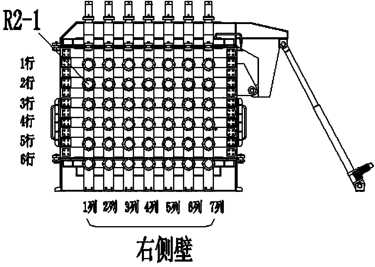
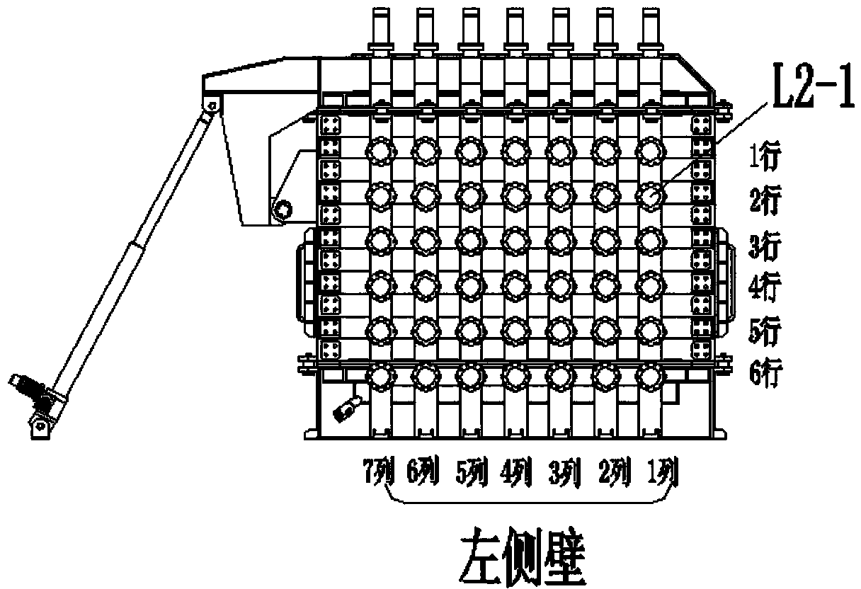
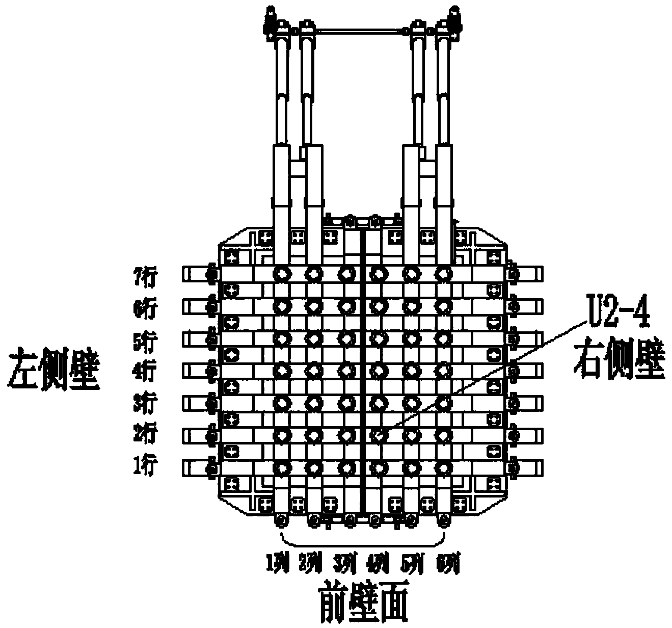
[0025] A hydraulic system for a tunnel simulation loading test platform of the present invention includes a hydraulic station, an actuator, a control system,

[0026] Such as Figure 8 As shown, the hydraulic station includes a constant pressure variable pump 11, a motor 12, a display element 13 and auxiliary devices. The variable pump and motor realize the oil supply function of the system. The maximum working pressure of the constant pressure variable pump in the system is 25Mpa, the working pressure is 20Mpa, the maximum flow rate is 80L / min, and the displacement is 63Ml / r. The rated power of the motor used is 37KW, and the speed is 1440r / min. The display components include digital pressure gauge, oil filter clogging alarm, oil temperature alarm, etc., which realize the conversion of hydraulic signal to electrical signal, and are convenient to cooperate with the electronic...


PUM


Abstract

The invention discloses a hydraulic system for a tunnel loading test platform. The hydraulic system comprises a hydraulic station, an actuating mechanism and a control system, wherein the hydraulic station comprises a constant-pressure variable pump, a motor, a display element and an auxiliary device; the actuating mechanism is a spliced loading device consisting of a hydraulic cylinder, a push plate and a push rod, and the hydraulic cylinder, the push plate and the push rod are connected with one another in a threading manner; the entire spliced loading device is controlled by the control system; the control system consists of a central control element and an auxiliary control element, the auxiliary control element is a bottom layer electromagnetic valve and used for directly controlling the loading and unloading of the hydraulic cylinder; the central control element is an electro-hydraulic servo valve element and a pressure reduction-reversing electromagnetic valve element; when in low-pressure loading, the electro-hydraulic servo valve element is adopted, so that the hydraulic oil is conveyed from an oil supply circuit to the bottom layer electromagnetic valve; when in high-pressure loading, the pressure reduction-reversing electromagnetic valve element is adopted, so that the hydraulic oil enters the bottom layer electromagnetic valve through an upper electromagnetic reversing valve after being stabilized by a pressure reduction valve through the oil supply circuit.

Description

technical field [0001] The invention belongs to underground engineering simulation test technology, in particular to the design of a set of hydraulic system based on tunnel loading test platform, which is used to realize the hydraulic loading and unloading function of the test platform. Background technique [0002] The indoor simulation test device for the interaction between the tunnel structure and the surrounding rock has been well studied at home and abroad. Each test device also has its corresponding hydraulic system, and the hydraulic system of this type of test device is small in size and does not involve the design of the loading strategy. , often rely on the electro-hydraulic servo valve as a key component to realize oil pressure loading and unloading, the system is simple, and the means of control is single. However, with the improvement of the design of the indoor simulation test device and the expansion of the scale, it is necessary to gradually put up the test ...

Claims


Application Information

Patent Timeline
IPC IPC(8): F15B11/00
Inventor 李长春延皓张金英高攀洪开荣母东杰邹翀李文杰杨雪松李竞黄静陈策李磊刘沁
Owner BEIJING JIAOTONG UNIV
Learn More