Hydraulic valve arrangement and hydraulic machine arrangement having same

A technology of mechanical device and valve device, applied in the field of hydraulic valve device, can solve the problems of high risk of pressure distortion, distortion of control pressure hydraulic pump power adjustment, and high maintenance technology, and achieve the effect of reducing the cost of maintenance technology

Active Publication Date: 2014-05-07
ROBERT BOSCH GMBH
View PDF6 Cites 5 Cited by
  • Summary
  • Abstract
  • Description
  • Claims
  • Application Information

AI Technical Summary

Problems solved by technology

Since the control pressure is applied to the valve piston of the control valve, a distortion of the control pressure leads to a distortion of the power regulation of the hydraulic pump
[0007] Both solutions therefore have the disadvantage that the risk of control pressure distortion is high, since the pressure medium channels can easily incorporate dirt particles entrained in the pressure medium volume flow
As a result, the removal of dirt from the pressure medium channel itself leads to high maintenance costs and interruption of the proper operation of the valve arrangement.

Method used


Image

  • Hydraulic valve arrangement and hydraulic machine arrangement having same
  • Hydraulic valve arrangement and hydraulic machine arrangement having same
  • Hydraulic valve arrangement and hydraulic machine arrangement having same

Examples


Embodiment Construction

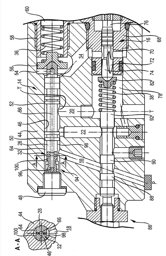
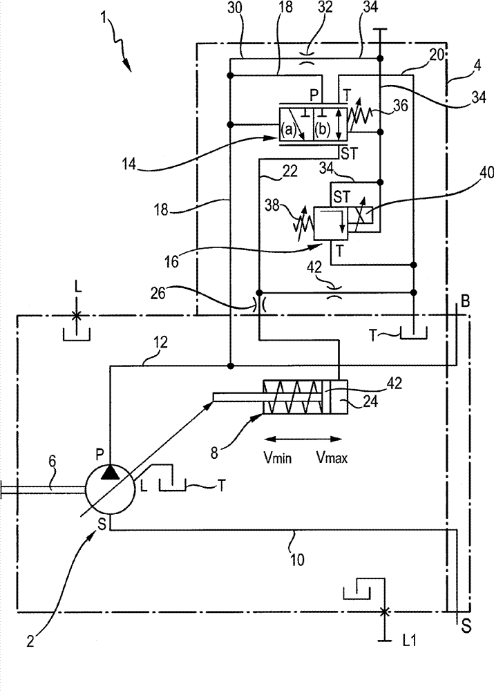
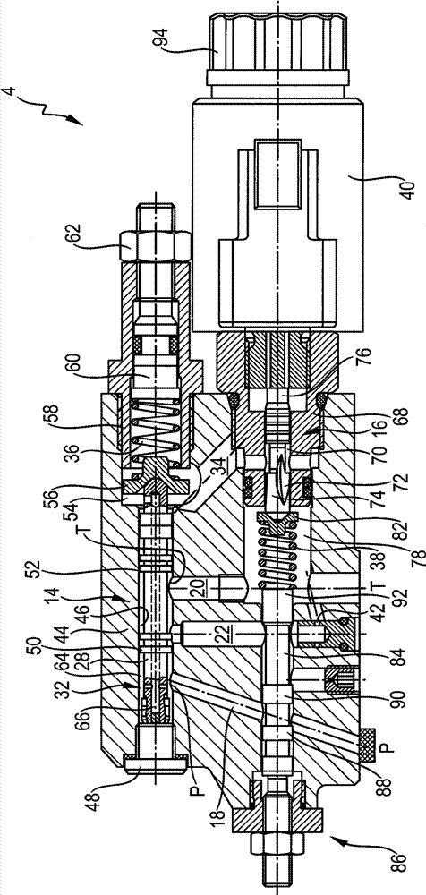
[0037] according to figure 1 , The hydraulic pump device 1 has a hydraulic pump 2 and a hydraulic valve device 4. The hydraulic pump 2 is designed as an adjustable axial piston machine with a swash plate structure. The axial piston machine has a drive shaft 6 through which the axial piston machine can be coupled with a drive motor. In addition, the axial piston machine has a suction connection S and a pressure connection P. The axial piston engine is driven in a closed circuit and has a leakage connection L in order to output the leakage flow, which is connected to a pressure medium outlet, in particular a tank T, via a leakage line. Furthermore, the hydraulic pump 2 has an adjusting device 8 designed as an adjusting cylinder. The piston rod of the adjusting device 8 is coupled with a swing cradle (not shown) of the hydraulic pump 2. The adjustment device 8 can adjust the swing angle of the hydraulic pump 2 and its geometrical displacement or supply flow.

[0038] The suction...


PUM


Abstract

The invention discloses a hydraulic valve arrangement, especially a regulating valve arrangement of a hydraulic machine whcihi s particularly a hydraulic pump. The valve arrangement has at least one valve. A valve body of the valve is penetrated by a pressure medium passage which has a minimum cross section, and, thus in normal operation, controls pressure downstream of the minimum cross section with a pressure acting at a pressure port of the valve. The minimum cross section is arranged close to a pressure medium passage mouth which is arranged upstream or is configured to be subjected to the high pressure. Additionally, a hydraulic machine arrangement, in particular a pump arrangement, includes the hydraulic valve arrangement.

Description

Technical field [0001] The present invention relates to a hydraulic valve device according to the preamble of claim 1, especially for pressure regulation and / or volume flow regulation of hydraulic machinery, especially hydraulic pumps, and a hydraulic valve device according to claim 15 A hydraulic mechanical device with such a valve device. Background technique [0002] Such a hydraulic valve device is known from the applicant's data sheet RD 92703 / 08.11 and is especially used in the pressure regulation and supply flow regulation of hydraulic pumps, especially axial piston pumps. The valve device has a first valve or a supply flow regulating valve through which the supply flow of the hydraulic pump is adjustable. The adjustment is realized by applying an adjustment pressure adjusted by the supply flow adjustment valve to the working chamber of the adjustment device of the hydraulic pump, which results in adjustment of the geometric displacement or supply flow of the hydraulic pu...

Claims


Application Information

Patent Timeline
Patent Type & Authority Applications(China)
IPC IPC(8): F15B11/08F15B13/044F15B13/04
CPCF15B2211/20553F04B1/2042F15B2013/008F15B20/008F04B49/22F15B2211/8633F16K11/0716F04B49/002F04B49/08
Inventor M.泽茨F.诺特C.迪博尔德
Owner ROBERT BOSCH GMBH
Why Eureka
Try Eureka