
Pipeline leakage monitoring system and method

A technology of pipeline leakage and monitoring system, applied in pipeline systems, mechanical equipment, gas/liquid distribution and storage, etc., can solve problems such as high cost, difficult to achieve, and inability to accurately measure pressure changes, and achieve fast response speed. , long service life, convenient long-distance transmission and processing effect

Inactive Publication Date: 2014-05-07
PETROCHINA CO LTD
View PDF6 Cites 15 Cited by
  • Summary
  • Abstract
  • Description
  • Claims
  • Application Information

AI Technical Summary

Problems solved by technology

Under normal circumstances, when the pipeline is affected by temperature and environment, the pressure signal collected by the pressure transmitter only accounts for a small proportion of the full-scale output value, so the pressure change with a small output value cannot be accurately measured. take measurements
[0006] The gas-sensing method can locate the leak location and monitor tiny leaks, but it needs to be arranged in high density along the pipeline, which is costly and difficult to implement

Method used


Image

  • Pipeline leakage monitoring system and method
  • Pipeline leakage monitoring system and method
  • Pipeline leakage monitoring system and method

Examples


Embodiment Construction

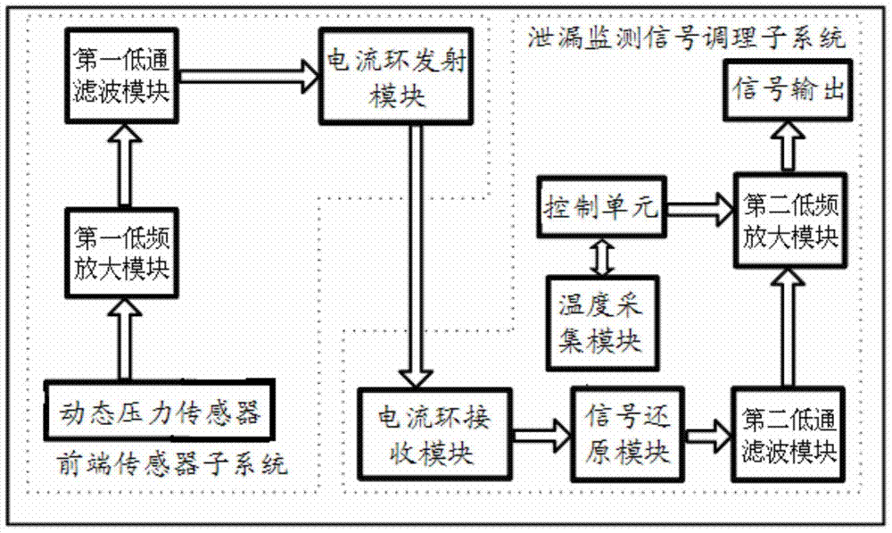
[0047] see figure 1 , a pipeline leakage monitoring system provided by an embodiment of the present invention includes a front-end sensor subsystem and a leakage monitoring signal conditioning subsystem; After performing amplification and filtering processing, it is transformed into a current signal, and then the current signal is sent to the detection signal conditioning subsystem; the leakage monitoring signal conditioning subsystem is used to convert the received current signal into a dynamic pressure signal, Then the dynamic pressure signal is amplified and filtered to collect data.

[0048] Wherein, the front-end sensor subsystem includes: a dynamic pressure sensor, a first low-frequency amplification module, a first low-pass filter module, and a current loop transmitter module. The dynamic pressure sensor is used to collect the dynamic pressure signal generated by the dynamic pressure change of the pipeline at the moment of leakage; the dynamic pressure sensor is a dyna...


PUM


Abstract

The invention discloses a pipeline leakage monitoring system which comprises a front end sensor subsystem and a leakage monitoring signal conditioning subsystem with a current loop receiving module, a signal restore module, a second lower-frequency amplification module and a second lowpass filter module. The front end sensor subsystem is used for amplifying and filtering dynamic pressure signals generated due to dynamic pressure changes at the leakage moment of a pipeline and then converting the dynamic pressure signals into current signals, the current signals are transmitted to the leakage monitoring signal conditioning subsystem, the leakage monitoring signal conditioning subsystem converts the received current signals into dynamic pressure signals, and then amplifies and filters the dynamic pressure signals, and then the dynamic pressure data of the pipeline leakage are recorded. The invention further discloses a pipeline leakage monitoring method. According to the pipeline leakage monitoring system and method, a sensing system is high in sensitivity, capable of responding to tiny signals, high in signal to noise ratio, compact in structure, long in service life, safe and reliable, and cannot be interfered by electromagnetism easily.

Description

technical field [0001] The invention relates to the technical field of pipeline monitoring, in particular to a pipeline leakage monitoring system and method. Background technique [0002] The oil pipeline is composed of pipelines, equipment and accessories. According to the needs of the process, it is equipped with corresponding oil pump units, designed and installed as a complete pipeline system to complete the oil loading and unloading and transportation tasks. [0003] The earlier pipeline leakage monitoring technology includes using the flow balance method to monitor the flow difference between the inlet and outlet of the pipeline to judge leakage; installing pressure transmitters at oil pumping stations to collect pressure data to judge whether there is leakage; installing gas sensors along the pipeline to monitor leakage The combustible gas in the soil pores can be used to judge whether there is a leak. [0004] The flow balance method can detect small leaks, but the ...

Claims


Application Information

Patent Timeline
IPC IPC(8): F17D5/06
Inventor 许斌刘广文谭东杰王洪超吴家勇胡森王立坤熊敏马云宾杨喜良
Owner PETROCHINA CO LTD
Learn More