Phase change heat storage type electric heating floor

An electric heating floor, phase change heat storage technology, applied in the field of building decoration, can solve the problems of poor waterproof sealing, poor heat transfer effect, complex structure and installation, etc.

Inactive Publication Date: 2014-05-07
江苏德威木业有限公司
View PDF18 Cites 8 Cited by
  • Summary
  • Abstract
  • Description
  • Claims
  • Application Information

AI Technical Summary

Problems solved by technology

It can be seen from this that the floor heating floor also has the following disadvantages: the one is that the box seat 41 of its connection socket 4 is connected with the lower gland 45 by screws 46, and its waterproof sealing is relatively poor, and there is a potential safety hazard
Second, the document does not disclose the specific structure of the conductive connecting rod
It can be seen that the heat emitted by the heating cable 10 of this device not only needs to pass through the packed bed, the pipeline 4, the concrete layer 7, the leveling layer 6 and the ground layer 5 successively before it can be transferred to the room. The area of ​​the outer

Method used


Image

  • Phase change heat storage type electric heating floor
  • Phase change heat storage type electric heating floor
  • Phase change heat storage type electric heating floor

Examples


Embodiment 1

[0126] (Example 1, phase change heat storage type electric heating floor)

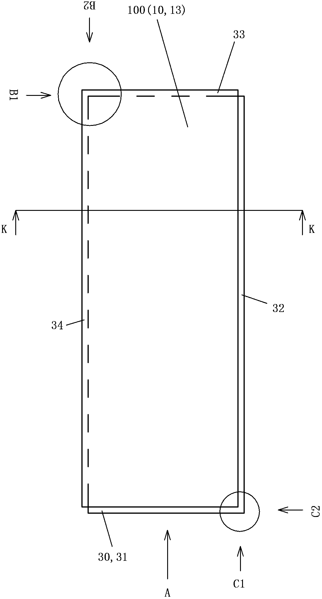
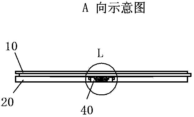
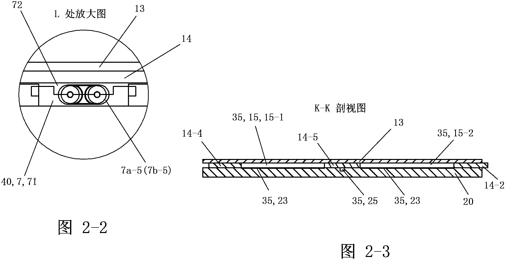
[0127] See Figure 1 to Figure 2-3 , The phase change thermal storage type electric heating floor 100 of the present invention is mainly composed of the floor main body 3 , the electric heating assembly 40 and the phase change unit 90 . The floor main body 3 is substantially in the shape of a plate-like cuboid, and is composed of a panel member 10 and a bottom plate 20 that are bonded and fixed together in the up and down direction at the peripheral parts. The interior of the floor main body 3 has a first installation space 35, and the first installation space The space 35 is jointly formed by the panel member 10 and the bottom plate 20 . The electric heater 5 and the phase change unit 90 of the electric heating assembly 40 are fixedly arranged in the first installation space 35 of the floor body 3 , and the overall shape formed by the electric heater 5 and the phase change unit 90 is consistent with ...

Embodiment 2)

[0195] The rest of this embodiment is the same as that of Embodiment 1, the difference being that there is no connection between the two inserting bars 81 of the double inserting bars 8 used to electrically connect two adjacent phase-change heat storage type electric heating floors. pieces, all of which are separate rods 81 (see Figure 20 ). The structural shapes of the two plungers 81 are basically the same.

Embodiment 3)

[0197] The rest of this embodiment is the same as that of Embodiment 1. The difference is that the plugging part 30 of this embodiment is formed during machining, and all the cut parts are cut on the bottom plate 20 to form a phase change heat storage type electric heating floor. The socket part 30.


PUM


Abstract

The invention discloses a phase change heat storage type electric heating floor. The phase change heat storage type electric heating floor comprises a floor main body and an electric heating assembly. Socket positions which are connected with the adjacent electric heating floor portions during usage are formed on the periphery of the floor. The phase change heat storage type electric heating floor is characterized by also comprising a flat phase change unit; the floor main body comprises a panel component and a base plate; the corresponding positions of the panel component and the base plate in the vertical direction are bonded and fixed together to form the floor main body, wherein the inside of the floor main body comprises the first installation space; the electric heating assembly comprises an electric heating piece, a transmission unit and connection sockets which are located at the front end and the rear end of the electric heating piece respectively and used for performing electrical connection externally; the electric heating piece and the phase change unit are fixedly arranged in the first installation space of the floor main body; the panel component, the electric heating piece, the phase change unit and the base plate are arranged in turn from top to bottom and are in close contact with each other in turn in the vertical direction.

Description

technical field [0001] The invention relates to a product in the field of building decoration, in particular to an electric heating floor. Background technique [0002] At present, the electric heating floor has become a new heating method, which is to lay the electric heating material in the floor, and heat the floor by heating the electric heating material in the floor to provide heat. However, in order to make the temperature in the room reach the level that people feel comfortable, it is necessary to energize the electric heating floor for a considerable period of time, so that the electric heating floor has the problems of large power consumption and slow temperature rise. Moreover, when the heating is stopped when the set temperature is reached, the indoor temperature drops rapidly. Thereby it is necessary to turn on the power supply again at regular intervals to increase the temperature of the electric heating floor, so that the indoor temperature is raised to the se...

Claims


Application Information

Patent Timeline
IPC IPC(8): F24D13/00F24D19/00E04F15/02
Inventor 葛林葛鑫琰
Owner 江苏德威木业有限公司
Why Eureka
Try Eureka