Manufacturing method of reticle

A manufacturing method and reticle technology, which is applied to the photoplate-making process, optics, instruments, etc. of the patterned surface, can solve problems such as complex processes, and achieve the effects of simple process, improved production efficiency, and improved alignment accuracy

Active Publication Date: 2014-05-07
BAZHOU YUNGU ELECTRONICS TECH CO LTD
View PDF5 Cites 5 Cited by
  • Summary
  • Abstract
  • Description
  • Claims
  • Application Information

AI Technical Summary

Problems solved by technology

The above-mentioned patent documents require multiple processes when makin

Method used


Image

  • Manufacturing method of reticle
  • Manufacturing method of reticle
  • Manufacturing method of reticle

Examples


Embodiment Construction

[0036] In order to make the objectives, technical solutions and advantages of the present invention clearer, the embodiments of the present invention will be further described in detail below with reference to the accompanying drawings.

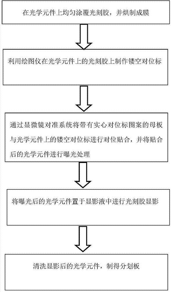
[0037] like figure 1 As shown, the present invention provides a manufacturing method of a reticle, wherein the manufacturing method comprises the following steps:

[0038] Step 1, uniformly coat the photoresist on the optical element, and bake it into a film; here, the thickness of the photoresist coating is 1 μm-10 μm, and the thickness of the photoresist film after baking is 1 μm~ 10 microns;

[0039] Step 2, using a laser plotter to make a hollow alignment mark on the photoresist on the optical element;

[0040] Step 3, aligning and bonding the motherboard with the solid alignment mark pattern and the hollow alignment mark on the optical element through the microscope alignment system, and exposing the bonded optical element;

[0041] ...


PUM


Abstract

The invention discloses a manufacturing method of a reticle. The method comprises the following steps: uniformly coating a photoresist on an optical element, and baking to form a film; making a hollow counterpoint mark on the photoresist of the optical element by use of a plotter; attaching a motherboard with a solid counterpoint mark pattern to the hollow counterpoint mark on the optical element through a microscope aligning system in a counterpoint mode, and performing exposure processing on the optical element after attachment; placing the optical element after exposure in a developing solvent for photoresist development; and cleaning the optical element after the development, and preparing the reticle. According to the invention, the optical element is coated by a black glue or a dark-color photoresist, and the hollow counterpoint mark is made on the photoresist by use of the laser plotter so that accurate positioning attachment between the motherboard and the optical element can be realized, the qualified rate of the reticle is improved, and the manufacturing process is simple.

Description

technical field [0001] The present invention relates to the technical field of reticle, in particular to a method for manufacturing a reticle. Background technique [0002] The reticle is generally installed on the focal plane of the right eyepiece of the telescope, such as Figure 4 As shown, it is a thin glass with a very thin surface engraved with dense bit lines. Since this thin glass theoretically also participates in imaging, extending the focal length of the objective lens will affect the length of the right eyepiece more or less. less impact. The reticle requires extremely high cleanliness, and any tiny dust will produce large black spots during observation; at the same time, the installation position of the reticle requires extremely high accuracy (the deviation between the center of the optical glass and the center of the pattern is ±0.03mm), Therefore, try not to disassemble it as much as possible. If disassembled, it must be restored as it is. [0003] Chinese ...

Claims


Application Information

Patent Timeline
IPC IPC(8): G02B27/32G03F9/00G02B23/00
Inventor 吴空物王静
Owner BAZHOU YUNGU ELECTRONICS TECH CO LTD
Why Eureka
Try Eureka