Power module encapsulating structure

A packaging structure and power module technology, applied in the field of power electronics, can solve the problems of difficult automation and consistency of process methods and control

Active Publication Date: 2014-05-07
STARPOWER SEMICON
View PDF4 Cites 7 Cited by
  • Summary
  • Abstract
  • Description
  • Claims
  • Application Information

AI Technical Summary

Problems solved by technology

[0002] Traditional power modules use signal leads or bonding wires to realize the connection between the power part and the signal part. If signal leads are used for connection, insulating materials such as silicone tubes are generally used to cover the outside of the leads. The length control of the silicone tube and the action of the casing need to be manually After completion, the signal leads and signal terminals must be welded together, which generally needs to be done manually or by machine one by one, so it is difficult to achieve automation and consistency in process methods and control

Method used


Image

  • Power module encapsulating structure
  • Power module encapsulating structure
  • Power module encapsulating structure

Examples


Embodiment

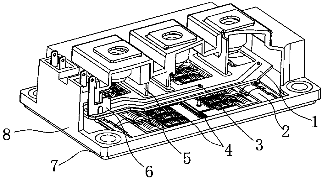
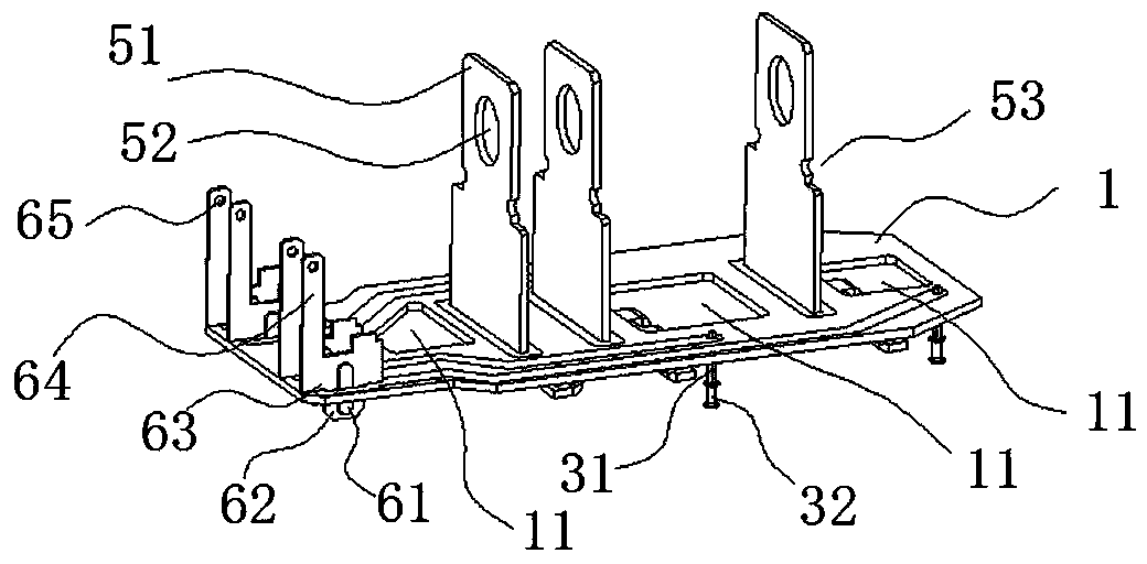
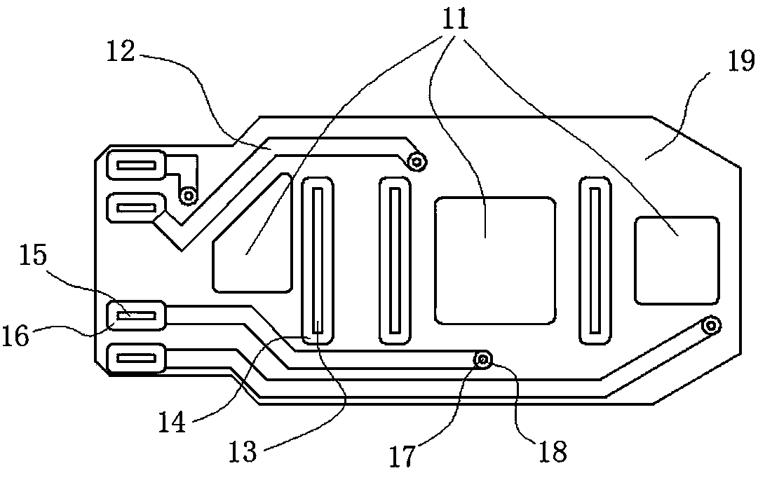
[0029] Example: figure 1 As shown, in the power module, the DBC2 with the chip and the bonding wire is welded to the substrate 7, and the circuit board 1 on which the power terminal 5, the signal terminal 6 and the signal lead frame 3 are fixed passes through the power terminal pin and the signal lead frame After the feet are welded to the DBC, the whole module is fixed and closed through the shell. There is an opening on the casing, and the power terminal and the signal terminal protrude through the opening to connect with the external application terminal. In this structure, there are 2 signal terminals leading to the gates of the upper tube and the lower tube respectively, and 2 signal terminals respectively leading to the emitters of the upper tube and the lower tube. The signal terminal is connected with the corresponding signal lead frame through the circuit design of the circuit board, and the signal lead frame is welded and connected with the corresponding position on...


PUM


Abstract

A power module encapsulating structure mainly comprises DBC, the DBC is provided with chips and bonding wires and is welded on a substrate, power terminals, signal terminals and signal frames are fixed to a circuit board, the circuit board is welded on the DBC through power terminal pins and signal frame pins, an outer shell fixes and seals a whole module, and the outer shell is provided with an opening allowing the power terminals and signal terminals to stretch out and be connected with external application terminals. Two signal terminals are led to a gate electrode of an upper tube and a gate electrode of a lower tube respectively, and the other two signal terminals are led to an emitting electrode of the upper tube and an emitting electrode of the lower tube respectively. Circuits on the circuit board enable the signal terminals and the corresponding signal frames to be communicated, and the signal frames are welded and communicated with the corresponding positions on the DBC. Three power terminals are fixed through the circuit board and are welded and communicated with the corresponding positions on the DBC. The power module encapsulating structure has the advantages of being simple in structure, convenient to mount and use and simple in manufacturing technology, and improving encapsulating precision and using reliability.

Description

technical field [0001] The invention relates to a package structure of a power module, which belongs to the technical field of power electronics. Background technique [0002] Traditional power modules use signal leads or bonding wires to realize the connection between the power part and the signal part. If signal leads are used for connection, insulating materials such as silicone tubes are generally used to cover the outside of the leads. The length control of the silicone tube and the action of the casing need to be manually After completion, the signal leads and signal terminals need to be welded together, which generally needs to be carried out one by one by hand or machine, so it is difficult to achieve automation and consistency in process methods and control. Contents of the invention [0003] The purpose of the present invention is to overcome the shortcomings of the prior art, and provide a power module packaging structure with simple structure, convenient us...

Claims


Application Information

Patent Timeline
Patent Type & Authority Applications(China)
IPC IPC(8): H01L25/07H01L25/16H01L23/498
CPCH01L2224/49111H01L2224/48139H01L2224/48227H01L2224/0603
Inventor 陈明晔
Owner STARPOWER SEMICON
Why Eureka
Try Eureka