

Rotor circuit double-ended excitation type hybrid excitation electrical machine
A hybrid excitation motor and rotor technology, which is applied to synchronous motors with static armatures and rotating magnets, synchronous machine parts, magnetic circuit rotating parts, etc., can solve the problem of uneven distribution of rotor magnetic field and long axial magnetic path. , local saturation and other problems, to achieve the effect of eliminating the rotating rectifier part, improving reliability, and fully utilizing
- Summary
- Abstract
- Description
- Claims
- Application Information
AI Technical Summary
Problems solved by technology
Method used
Image

Examples
Embodiment Construction
[0037] Embodiments of the invention will be described below in conjunction with the accompanying drawings
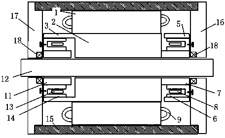
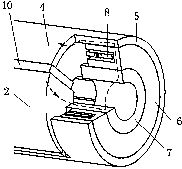
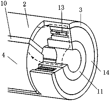
[0038] The structure of the hybrid excitation synchronous motor with double-terminal excitation of the rotor circuit is as follows: figure 1 , figure 2 , image 3 As shown, the present invention is improved on the basis of a common tangential permanent magnet synchronous motor, including a casing 15, the casing 15 is equipped with an armature core 1, the armature core 1 is a ring, and the motor The outer wall of the armature core 1 is in contact with the inner wall of the casing 15, the inner wall of the armature core 1 is radially slotted along the circumferential direction, and the armature winding 9 is arranged in the slot; as Figure 4 It is the structural diagram of the rotor and the excitation device of the motor, with the rotating shaft 12 as the center, the N-pole yoke 2, the permanent magnet 10, the S-pole yoke 4, and the permanent magnet 10 are fixed on the...
PUM
 Abstract
Description
Claims
Application Information