Rotary electrostatic generator

A generator, rotary technology, applied in the directions of triboelectric generators, battery circuit devices, current collectors, etc., can solve the problems of inability to supply power with small portable electronic devices, high starting power, and heavy weight, and achieve high energy conversion efficiency, The effect of low cost and efficient utilization

Active Publication Date: 2014-05-07
BEIJING INST OF NANOENERGY & NANOSYST
View PDF5 Cites 38 Cited by
  • Summary
  • Abstract
  • Description
  • Claims
  • Application Information

AI Technical Summary

Problems solved by technology

Due to their ubiquity, wind energy and hydropower have been widely regarded as very important renewable and non-polluting green energy sources. However, traditional wind energy tec...

Method used


Image

  • Rotary electrostatic generator
  • Rotary electrostatic generator
  • Rotary electrostatic generator

Examples


Embodiment approach

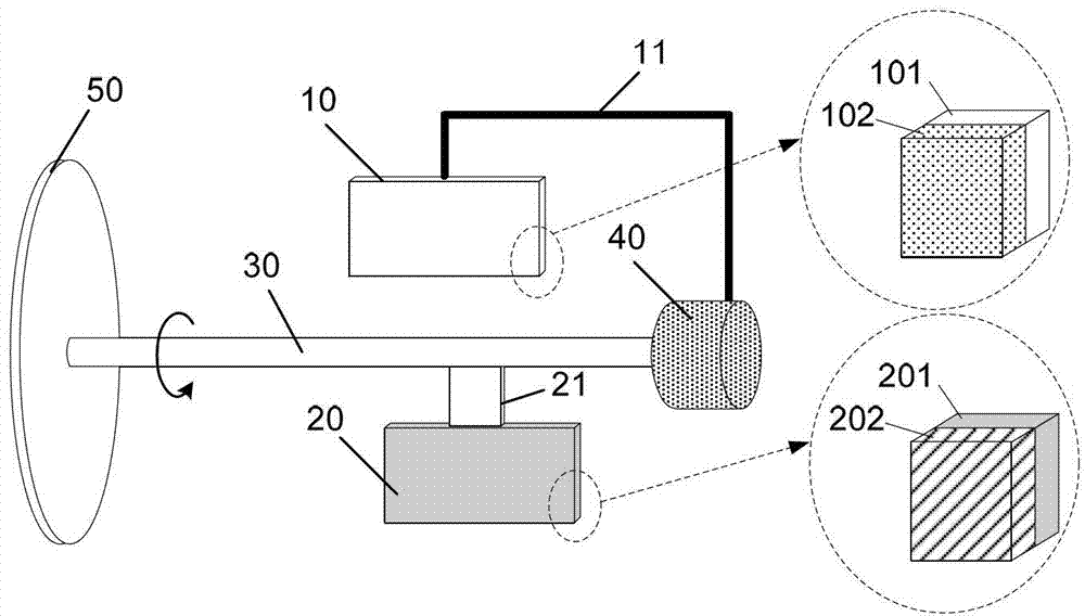
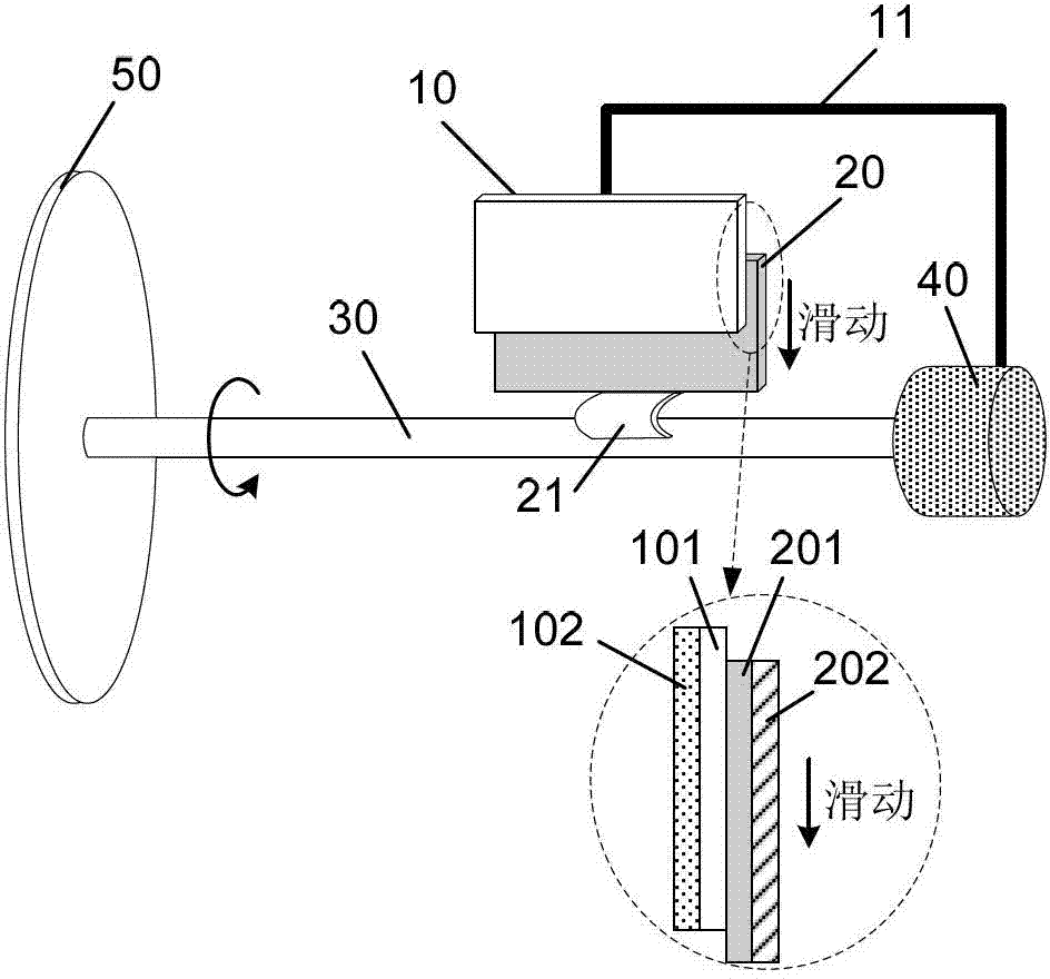
[0071] figure 1 and figure 2 Shown is a typical embodiment of the rotary electrostatic generator of the present invention, comprising: a power collection component 50, a stator 10, a stator support 11, a rotor 20, a rotor support 21, a rotating shaft 30 and a bearing 40; the power collection component 50 is located at one end of the rotating shaft 30, which can collect external mechanical energy and convert it into power to drive the rotating shaft 30 to rotate; the rotating shaft 30 is installed through the through hole of the bearing 40; one end of the rotor support 21 is fixed on the rotating shaft 30, and the other One end is connected with the rotor 20, one end of the stator support 11 is relatively fixed with the shell of the bearing 40, and the other end is connected with the stator 10, so that relative rotation can be formed between the stator 10 and the rotor 20, and when the rotor 20 turns to the position where the stator 10 is located position, at least partial su...

Embodiment 1

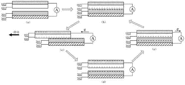
[0100] The structure of the rotary electrostatic generator in this embodiment is as follows figure 2 As shown, it includes: a wind-type power collection component composed of 20 blades; a stator formed by the first friction layer of polyimide layer and the first conductive layer of metal Cu film; the second friction layer of polyphthalate Rotor formed by allyl ester layer, second conductive layer Ag film; stator support formed by polyester rod; flexible rotor support made of rubber sheet; rotating shaft made of copper rod; contact with alloy bearing surface . Use a blower to blow the windmill to drive the rotor to rotate. When the rotor rotates to the position where the stator is, the second friction layer on the rotor contacts the first friction layer on the stator. After that, the rotor support tends to continue to rotate under the drive of the rotating shaft. Rotation, due to the blocking of the stator, the rotor support bends, as the shaft continues to rotate, the rotor ...

Embodiment 2

[0102] The structure of the generator see Figure 9 , including: a windmill 50 composed of three wind cups is located at the top of the rotating shaft 30; two sets of stators 10 made of Al plates are respectively fixed inside a rectangular frame-type stator support 11 made of polyacrylate, in order to facilitate maintenance Balanced, 4 stator supports are used, and these stator supports are distributed symmetrically around the shaft 30, 2 of which are used to fix the stator, and the other 2 are only for balancing; polytetrafluoroethylene (PTFE) film As the second friction layer on the rotor 20, a metal copper film is deposited on the back as the second conductive layer, and then adhered to the rotor support 21 made of polyethylene terephthalate (PET) flexible sheet , so that the metal copper film is sandwiched between the rotor support 21 and the second friction layer; the metal rotating shaft 30 is located at the center of the entire generator, and is fixed through the centra...


PUM


Abstract

The invention provides a rotary electrostatic generator, which comprises a power collecting component, a stator, a stator supporting member, a rotor, a rotor supporting member, a rotating shaft and a bearing, wherein the power collecting component is fixed on the rotating shaft, the rotating shaft, the rotor supporting member fixed on the rotating shaft and the rotor connected to the rotor supporting member are driven to rotate together by an external force, the rotor and the stator are enabled to be contacted with or separated from each other periodically, relative sliding friction is generated between a first friction layer and a second friction layer on the contact surface, and the friction area is changed, thereby being capable of generating electric signals and outputting the electric signals to an external circuit. The electric signal output not only can act as a power supply to drive electronic devices such as an LED, an LCD and the like or charge energy storage devices such as a lithium battery, a capacitor and the like, but also can be used for detecting the flow rate of a fluid in real time.

Description

technical field [0001] The invention relates to a generator, in particular to a rotary electrostatic generator which converts mechanical energy into electrical energy. Background technique [0002] With the rapid development of miniaturized and portable electronic devices, the development of emerging technologies that can directly convert energy in the environment into electricity has attracted increasing attention. There are many forms of mechanical energy in our life and surrounding environment, such as vehicle movement, human body motion, tide, wind energy, etc., the list goes on. Due to their ubiquity, wind energy and hydropower have been widely regarded as very important renewable and non-polluting green energy sources. However, traditional wind energy technology and hydroelectric generators have disadvantages such as large size, heavy weight, high cost, and high starting power. , cannot be used for power supply of small portable electronic devices. [0003] Therefore...

Claims


Application Information

Patent Timeline
IPC IPC(8): H02N1/04H02J7/14
Inventor 谢燕楠王思泓王中林
Owner BEIJING INST OF NANOENERGY & NANOSYST
Why Eureka
Try Eureka