Hydraulic drive device and system

A driving device and hydraulic technology, which is applied in fluid pressure actuators, servo motors, mechanical equipment, etc., can solve problems such as energy waste and hydraulic oil leakage, and achieve the effects of saving energy and improving pressure accuracy

Inactive Publication Date: 2014-05-14
BOSCH REXROTH (CHANGZHOU) CO LTD
View PDF10 Cites 0 Cited by
  • Summary
  • Abstract
  • Description
  • Claims
  • Application Information

AI Technical Summary

Problems solved by technology

However, since the bypass is fixed, hydraulic oil will always leak through the bypass, which still results in wasted energy

Method used


Image

  • Hydraulic drive device and system
  • Hydraulic drive device and system

Examples


Embodiment Construction

[0024] In order to help those skilled in the art to accurately understand the claimed subject matter of the present invention, the specific implementation manners of the present invention will be described in detail below in conjunction with the accompanying drawings.

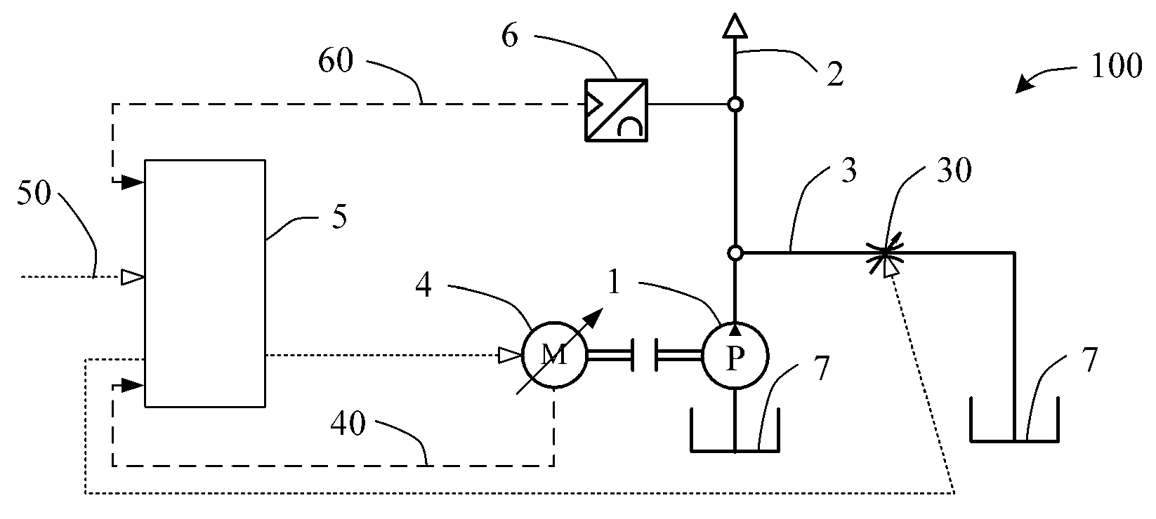
[0025] figure 1 A schematic diagram showing a hydraulic drive device according to an embodiment of the present invention. Such as figure 1 As shown, a hydraulic drive device 100 according to a specific embodiment of the present invention includes a hydraulic pump 1, a hydraulic bypass 3 and a control unit 5, wherein the hydraulic pump 1 pumps hydraulic fluid from the reservoir 7 for connection to the required The hydraulic output line 2 of the driven hydraulic actuator, the hydraulic bypass 3 is connected from the hydraulic output line 2 to the liquid reservoir 7, the hydraulic bypass 3 is provided with an adjustable flow device 30, the adjustable flow device 30 can be a system , valves or other devices. The...


PUM


Abstract

The invention discloses a hydraulic drive device and system. The device comprises a hydraulic pump, a hydraulic bypass and a control unit. The hydraulic pump pumps hydraulic fluids from a reservoir to a hydraulic outputting line, the hydraulic bypass is connected with the reservoir through the hydraulic outputting line, an adjustable flow unit is arranged in the hydraulic bypass, and the control unit controls the flow unit to adjust the flow of the hydraulic fluids in the hydraulic bypass according to operation conditions. According to the hydraulic drive system, the hydraulic outputting line is connected with one or more hydraulic actuators. By means of the hydraulic drive device and system, the flow of the hydraulic fluids in the hydraulic bypass can be adjusted, the pressure accuracy is improved, and energy is saved.

Description

technical field [0001] The invention relates to the technical field of hydraulic drive, in particular to a hydraulic drive device and system. Background technique [0002] In order to achieve predetermined actions in mechanical equipment, hydraulic drive devices are often used. For example, on an injection molding machine, after closing the mold, it is necessary to inject heated and molten plastic into the cavity of the mold. Then, it is necessary to keep the pressure to maintain the position of the hydraulic actuator for injection for a period of time, wait for the injected part to cool and form in the cavity, then open the mold to take out the part, and then close the mold for the next injection. Therefore, in the injection molding machine, actions such as injection, mold clamping, and mold opening need to be realized, and these actions can be realized by using a hydraulic drive device. However, each action has different requirements for the required hydraulic flow and p...

Claims


Application Information

Patent Timeline
Patent Type & Authority Applications(China)
IPC IPC(8): F15B11/02
Inventor 陈永伯王伟杨大鹏刘洋孙培
Owner BOSCH REXROTH (CHANGZHOU) CO LTD
Why Eureka
Try Eureka