High-pressure air supply valve with pressure difference control function and air scavenging method

A technology of high-pressure air and control functions, which is applied in the direction of valve lift, valve details, valve devices, etc., can solve the problem that the main valve cannot adjust the blowing air supply flow, etc., to avoid excessive blowing flow, compact structure, and maintainability Good results

Active Publication Date: 2014-05-14
CHINA SHIP DEV & DESIGN CENT
View PDF5 Cites 15 Cited by
  • Summary
  • Abstract
  • Description
  • Claims
  • Application Information

AI Technical Summary

Problems solved by technology

[0009] The technical problem to be solved by the present invention is to provide an all-mechanical high-pressure air valve that can automatically adjust the air supply flow rate according to the pressure difference between the ballast water tank and the external seawater, aiming at the inability of the existing main valve to adjust the air supply flow rate. Main valve and air blowing method

Method used


Image

  • High-pressure air supply valve with pressure difference control function and air scavenging method
  • High-pressure air supply valve with pressure difference control function and air scavenging method

Examples


Embodiment Construction

[0038] The main technical index of this invention is as follows:

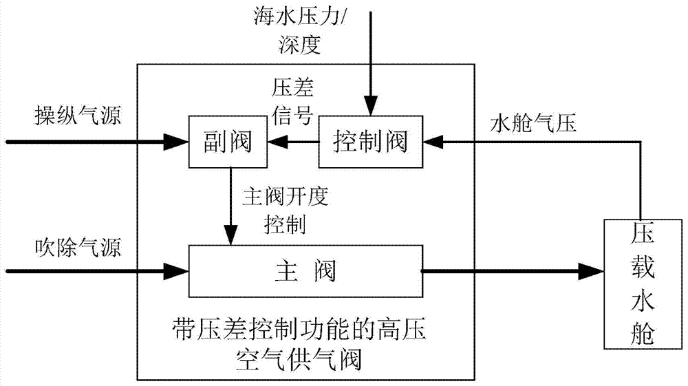
[0039] figure 1 It is the working flow diagram of the high-pressure air supply valve with differential pressure control function of the present invention. The high-pressure air supply valve with differential pressure control function is composed of three parts: main valve, auxiliary valve and control valve. The main valve is the main channel for high-pressure air supply, and the auxiliary valve is used for the opening and closing operation of the main valve. The control valve controls the air supply volume of the main valve by sensing the pressure difference between the ballast water tank and the seawater outside the ship.

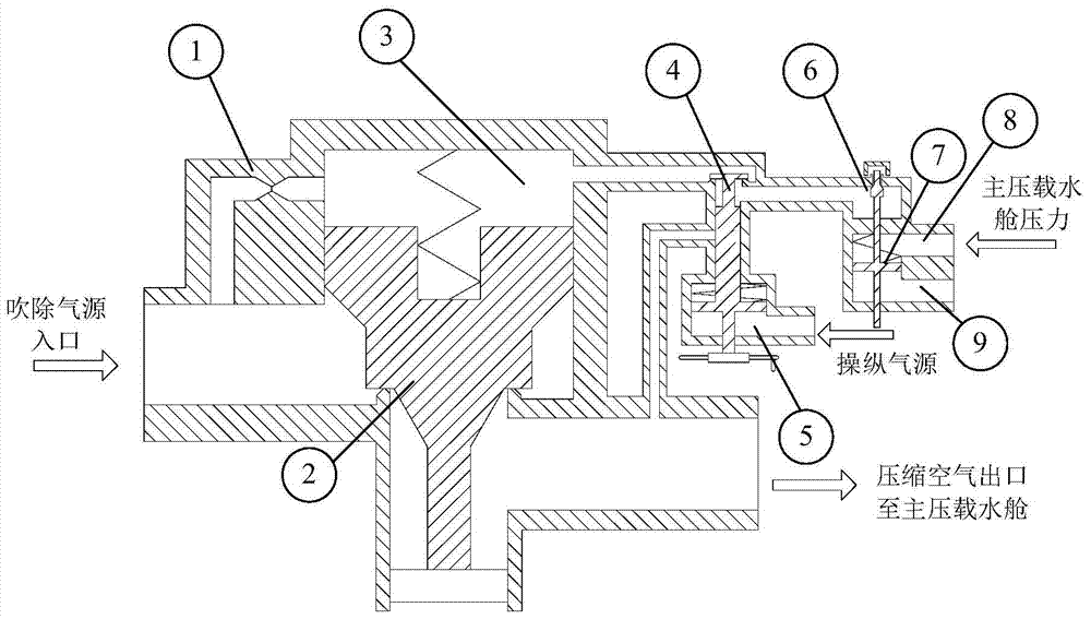
[0040] figure 2 It is a schematic diagram of the structure of the high-pressure air supply valve with differential pressure control function of the present invention, which is composed of three parts: the main valve, the auxiliary valve and the control valve; the main valve includes the m...


PUM


Abstract

The invention relates to a high-pressure air supply valve with a pressure difference control function and an air scavenging method. According to the method, the pressure difference between a water ballast space and outside seawater can be kept stable during air scavenging. The high-pressure air supply valve is composed of a main valve body, an auxiliary valve body and a control valve body, wherein the main valve body is the main channel for high-pressure air supply, high-pressure air enters the water ballast space through the main valve body, the opening degree of a valve element of the main valve body is automatically adjusted through the pressure difference between an upper cavity of the valve element and a lower cavity of the valve element, and then the adjustment of supplied airflow is achieved; the auxiliary valve body is used for controlling the opening and closing of the main valve body and has both a pneumatic control function and a manual control function; the control valve body is used for sensing the pressure difference between the interior of the water ballast space and the exterior of the water ballast space, controlling the opening degree of the valve element of the main valve body, and controlling the opening degree of a valve element of the control valve body according to the pressure difference to enable the flow of compressed air in the upper cavity of the valve element of the main valve body to be changed, then the change of pressure of the upper cavity of the valve element of the main valve body is caused, and finally the opening position of the valve element of the main valve body is controlled. According to the high-pressure air supply valve, a fully-mechanical structure is adopted, no electrical element is used, remote operation can be achieved through compressed air, other power sources are not needed, and reliability is high.

Description

technical field [0001] The invention relates to a fully mechanical servo-controlled air supply flow regulating valve and an air blowing method, which can maintain the stability of the pressure difference between the ballast water tank and the external seawater during the emergency floating and blowing process of the aircraft. Background technique [0002] High-pressure air blowing off is an important means for emergency flotation of submarines and an important guarantee for the vitality of submarines. The current high-pressure air main valve only adopts opening and closing control, and does not have the function of flow adjustment. [0003] According to the design requirements of the high-pressure air blow-off system, the gas at the outlet of the blow-off pipeline should reach the local speed of sound to ensure the maximum blow-off flow rate. In addition to the flow area of ​​the pipeline, the larger the flow area, the greater the flow. [0004] The main valve currently com...

Claims


Application Information

Patent Timeline
Patent Type & Authority Applications(China)
IPC IPC(8): F16K31/122F16K31/60F16K27/02
CPCB63G8/22F16K1/00F16K31/1221F16K31/143
Inventor 周志杰张超张军军吴声敏郑国群
Owner CHINA SHIP DEV & DESIGN CENT
Why Eureka
Try Eureka