A Method for Acquiring Azimuth Parameters of Spaceborne Synthetic Aperture Radar Sliding Spotlight Mode

A technology of synthetic aperture radar and sliding beamforming, applied in the directions of radio wave reflection/re-radiation, utilization of re-radiation, measurement devices, etc., can solve the problems of large amount of calculation, complex operation, low efficiency, etc., and avoid echo simulation The effect of processing the verification process with imaging, simplifying the scheme design process, and improving the efficiency of engineering design

Active Publication Date: 2016-08-17
INST OF ELECTRONICS CHINESE ACAD OF SCI
View PDF2 Cites 0 Cited by
  • Summary
  • Abstract
  • Description
  • Claims
  • Application Information

AI Technical Summary

Problems solved by technology

[0009] In order to solve the defects of complex calculation, large amount of calculation, long time consumption and low efficiency in the prior art, the purpose of the present invention is to propose a design process for the length of the azimuth imaging band of the spaceborne sliding spotlight mode suitable for engineering applications, which can be used in the preliminary Avoid the process of echo simulation and imaging processing in the design of the scheme, and can ensure the reliability of the obtained parameter results and improve the efficiency of the obtained parameters

Method used


Image

  • A Method for Acquiring Azimuth Parameters of Spaceborne Synthetic Aperture Radar Sliding Spotlight Mode
  • A Method for Acquiring Azimuth Parameters of Spaceborne Synthetic Aperture Radar Sliding Spotlight Mode
  • A Method for Acquiring Azimuth Parameters of Spaceborne Synthetic Aperture Radar Sliding Spotlight Mode

Examples


Embodiment Construction

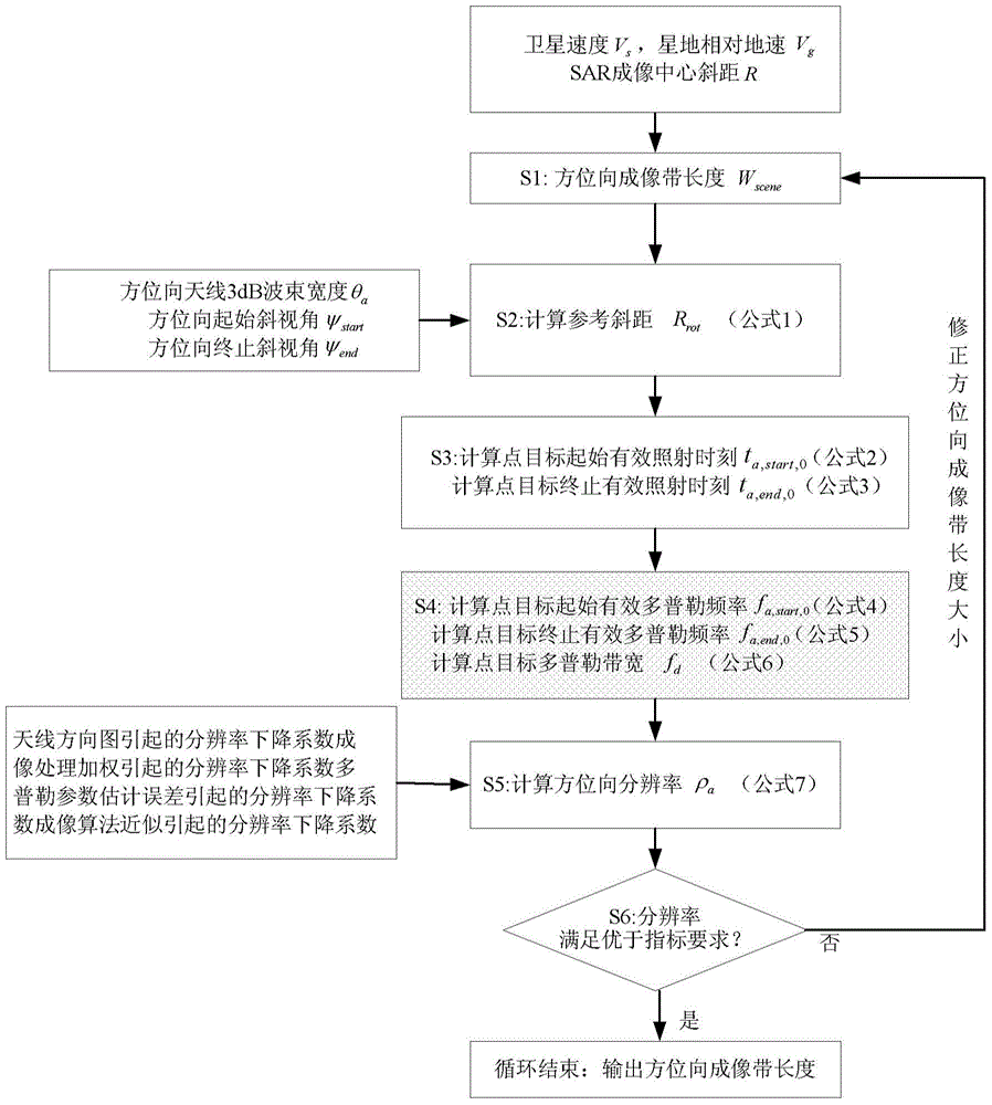
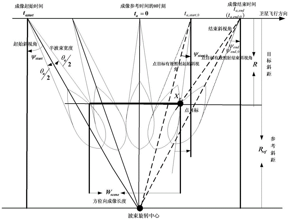
[0022] The following will combine the additional figure 1 and figure 2 The present invention will be described in detail.

[0023] The basic principle of spaceborne SAR sliding spotlight mode is as follows: figure 1 As shown, during a period of imaging time, the satellite flies along the orbit at a certain speed, controls the azimuth to point to the center of the beam, and makes the azimuth to the center of the beam at a certain initial oblique angle ψ start Start to rotate around the center of rotation, and the oblique angle reaches the end oblique angle ψ end end. In engineering, the center of rotation is a virtual point under the surface, and the slant distance corresponding to the center of rotation is greater than the slant distance of the target point. On the ground, the center of the beam moves from left to right, and slides over all targets in the imaging area in turn. , the thick black line in the middle of the figure is the imaging area. figure 1 The large soli...


PUM


Abstract

The invention provides an azimuth parameter obtaining method for a satellite-borne synthetic aperture radar in a sliding bunching mode. An azimuth initial imaging belt length, an antenna beamwidth, an initial squint angle, a terminate squint angle and a target slant distance are utilized to establish a reference slant distance model corresponding to a beam rotation center; reference slant distance data are obtained, and an effective irradiation time model corresponding to a point target is established according to the reference slant distance data; effective initial irradiation time and effective terminate irradiation time of the point target are obtained, and an effective Doppler frequency and Doppler bandwidth model corresponding to the point target is established according to the effective initial irradiation time and effective terminate irradiation time of the point target; initial effective Doppler frequency, terminate effective Doppler frequency, the Doppler bandwidth and the resolution declining coefficient corresponding to the point target are obtained, an azimuth resolution model corresponding to the point target is established according to the initial effective Doppler frequency, terminate effective Doppler frequency, the Doppler bandwidth and the resolution declining coefficient corresponding to the point target, and the azimuth resolution corresponding to the point target is obtained; when the azimuth resolution is larger than a resolution index requirement, the maximum azimuth imaging belt length datum is output.

Description

technical field [0001] The invention belongs to the field of space-borne synthetic aperture radar imaging, and relates to the acquisition technology of space-borne synthetic aperture radar (SAR) system parameters. Background technique [0002] The sliding spotlight mode of spaceborne synthetic aperture radar is the main mode to research and realize high-resolution and wide coverage spaceborne synthetic aperture radar imaging in recent years. quality spaceborne synthetic aperture radar images. However, due to the limited scanning capability of the antenna in azimuth direction, TerraSAR-X’s design of resolution and imaging band length is not high (1m×5km). The performance of the beam mode can be greatly improved (resolution better than 0.3m, imaging swath length better than 10km). However, the improvement of performance will lead to a great increase in the difficulty and complexity of parameter design, echo signal simulation and imaging processing. [0003] The range parame...

Claims


Application Information

Patent Timeline
Patent Type & Authority Patents(China)
IPC IPC(8): G01S13/90
CPCG01S7/4017G01S13/90G01S13/9047G01S13/9052
Inventor 吕继宇李海英王宇邓云凯
Owner INST OF ELECTRONICS CHINESE ACAD OF SCI
Why Eureka
Try Eureka