

Wavelength conversion apparatus and light emitting device
A wavelength conversion device and wavelength conversion technology, applied in the field of luminescence, can solve problems such as phosphor efficiency decline, colloid aging, affecting the performance and life of light-emitting devices, and achieve the effect of reducing temperature and improving thermal conductivity
- Summary
- Abstract
- Description
- Claims
- Application Information
AI Technical Summary
Problems solved by technology
Method used
Image

Examples
Embodiment Construction
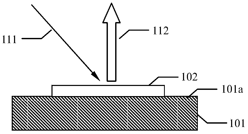
[0013] The present invention proposes a light emitting device, the structure of which is as follows figure 1 shown. The light emitting device includes a wavelength conversion layer 102 which is closely adhered to the surface 101 a of the thermally conductive substrate 101 . The light emitting device also includes an excitation light source (not shown in the figure), the excitation light 111 emitted by the excitation light source is incident on the wavelength conversion layer, and the wavelength conversion layer absorbs the excitation light and emits the received light 112 . In this embodiment, the surface 101a of the thermally conductive substrate to which the wavelength conversion layer is attached is reflective to the received light, which can reflect the light emitted by the wavelength conversion layer to the thermally conductive substrate 101, so that all the received light is directed toward the thermally conductive substrate 101. figure 1 Launch from above. The reflect...
PUM
| Property | Measurement | Unit |
|---|---|---|
| Thermal conductivity | aaaaa | aaaaa |
Abstract
Description
Claims
Application Information