Antenna assembly

A technology of antenna components and ground planes, which is used in antennas, slot antennas, antenna grounding devices, etc.

Inactive Publication Date: 2014-05-14
SHENZHEN FUTAIHONG PRECISION IND CO LTD +1
View PDF3 Cites 7 Cited by
  • Summary
  • Abstract
  • Description
  • Claims
  • Application Information

AI Technical Summary

Problems solved by technology

On the other hand, broadband antennas generally have a more complex structure, but since the appearance of the antenna module tend

Method used


Image

  • Antenna assembly
  • Antenna assembly
  • Antenna assembly

Examples


Embodiment Construction

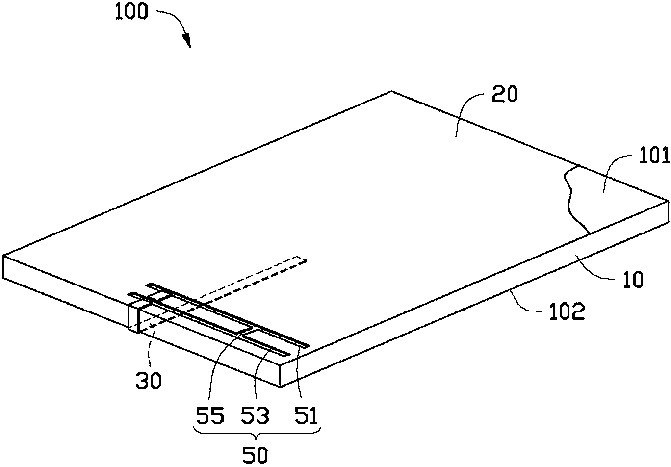
[0016] see figure 1 , a preferred embodiment of the present invention provides an antenna assembly 100, which can be applied in wireless communication devices such as mobile phones. The antenna assembly 100 includes a substrate 10 , a ground plane 20 , a feeding portion 30 and a radiation portion 50 .

[0017] The substrate 10 can be made of dielectric materials such as epoxy resin fiberglass (FR4). In this embodiment, the permittivity of the dielectric material is ε r . The substrate 10 is substantially a flat cuboid, including a top surface 101 and a bottom surface 102 opposite to the top surface 101 and parallel to each other.

[0018] The ground plane 20 is disposed on the top surface 101 of the substrate 10 for providing grounding for the antenna assembly 100 . In this embodiment, the ground plane 20 is a layer of conductive metal foil, such as copper foil, plated on the top surface 101 .

[0019] In this embodiment, the feeding part 30 is a microstrip line. The fee...


PUM


Abstract

The invention provides an antenna assembly comprising a substrate, a ground plane, a feed-in portion, and a radiation portion. The substrate comprises a top surface and a bottom surface arranged opposite to the top surface. The ground plane is disposed on the top surface and is used for connecting the antenna assembly with ground. The feed-in portion is disposed on the bottom surface and is partially extended to the ground plane. The radiation portion is formed by hollowing out the ground plane and is partially extended to an overlapped part of the feed-in portion and the ground plane so as to further form a slot antenna. The antenna assembly may widen the bandwidth of an antenna and is simultaneously convenient for a purpose of miniaturization development of wireless communication devices.

Description

technical field [0001] The invention relates to an antenna, in particular to an antenna component with a wide bandwidth. Background technique [0002] In a wireless communication device, the antenna device used to transmit and receive radio waves to transmit and exchange radio data signals is undoubtedly one of the most important components in the wireless communication device. [0003] In recent years, the emergence of various communication systems and applications using different operating frequency bands has led to the development of antenna design towards broadband antennas covering multiple system frequency bands. In order to ensure that the wireless communication device can perform signal transmission in various wireless communication systems using different operating frequency bands, the antenna device must be capable of transmitting and receiving signals of various frequencies. On the other hand, the broadband antenna generally has a relatively complex structure, bu...

Claims


Application Information

Patent Timeline
IPC IPC(8): H01Q1/48H01Q1/36H01Q5/01H01Q13/10H01Q5/10
Inventor 张子轩许倬纲
Owner SHENZHEN FUTAIHONG PRECISION IND CO LTD
Why Eureka
Try Eureka