
Hydraulically-loaded dual-power pulverizer

A hydraulic loading, dual power technology, applied in grain processing and other directions, can solve the problems of convenient manufacturing, high temperature of the grinding head spindle and grinding head bearing, and inconvenient maintenance, and achieves increased stability, equipment safety and stable operation. , the effect of improving efficiency

Active Publication Date: 2015-03-25
HAIAN TIANPENG MACHINERY MFG
View PDF7 Cites 0 Cited by
  • Summary
  • Abstract
  • Description
  • Claims
  • Application Information

AI Technical Summary

Problems solved by technology

The grinding head is installed on the swing arm that swings around a fixed point. Due to installation and manufacturing errors, the relative positions and gaps between each grinding head and the large grinding disc are different. During the adjustment process, due to the swing arc of the grinding head, grinding head, grinding roller and Large grinding discs often form an included angle, which changes the angle of the material layer at the occlusal point, and changes in force affect the quality of grinding and milling and the stability of work.
Chinese patent ultra-fine powder vertical roller mill, application number 200510017387.2, the grinding head is supported on the mobile trolley, and the grinding head is pressed against the edge of the large grinding disc under the action of the elastic pressure device. A grinding head motor is installed to drive the grinding rollers of the grinding head to rotate. There is a side airflow guiding air duct in the body to allow the gas entering the body to rotate and flow upwards. Although the relative positions and gaps between each grinding head and the large grinding disc can be the same, However, the grinding head body cannot be transferred from the body to the outside, which is inconvenient for maintenance
Moreover, in the above two inventions, the grinding head body is installed obliquely in the upper body, which is inconvenient to manufacture, and the grinding head spindle and the grinding head bearing do not use a cooling system. After the machine has been running for a period of time, the grinding head spindle and the grinding head bearing High temperature affects service life and operation stability

Method used


Image

  • Hydraulically-loaded dual-power pulverizer
  • Hydraulically-loaded dual-power pulverizer
  • Hydraulically-loaded dual-power pulverizer

Examples


Embodiment 1

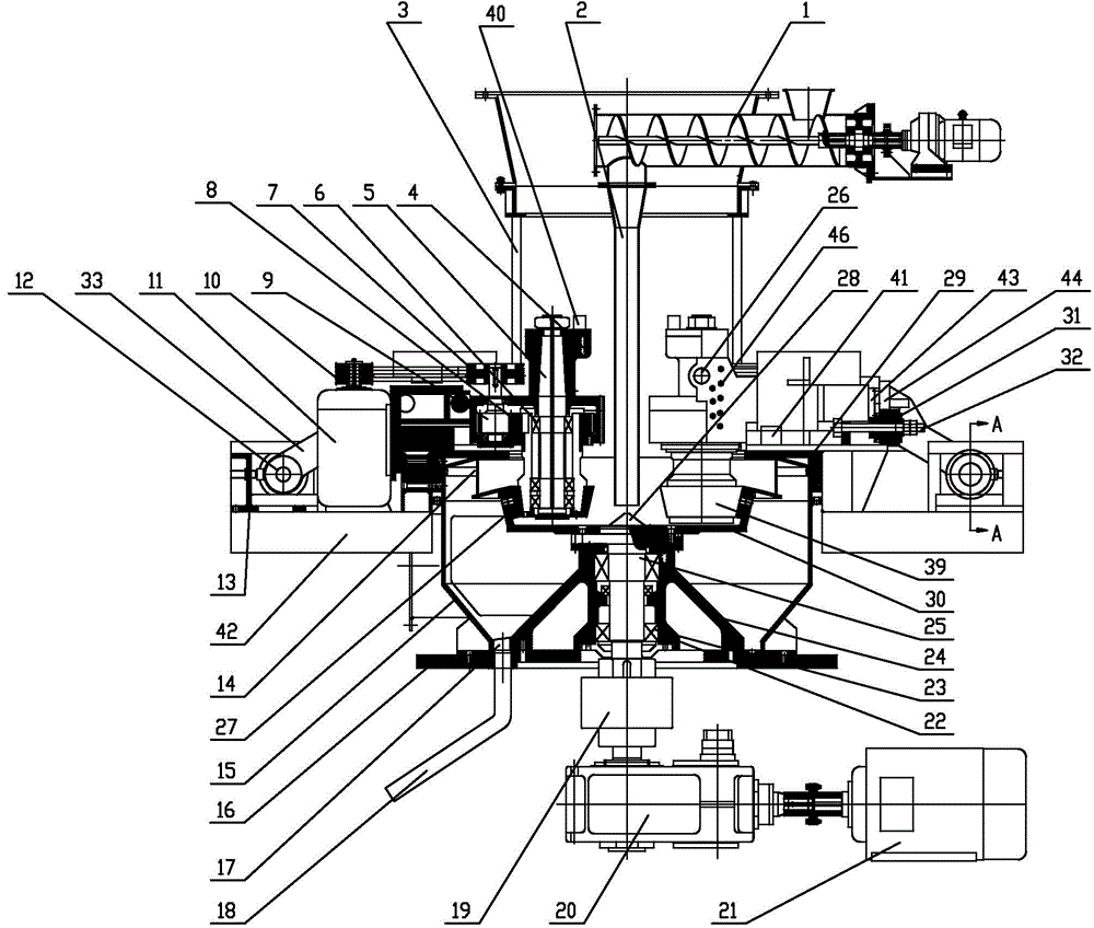
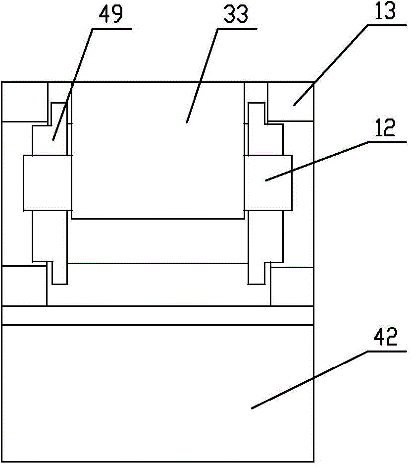
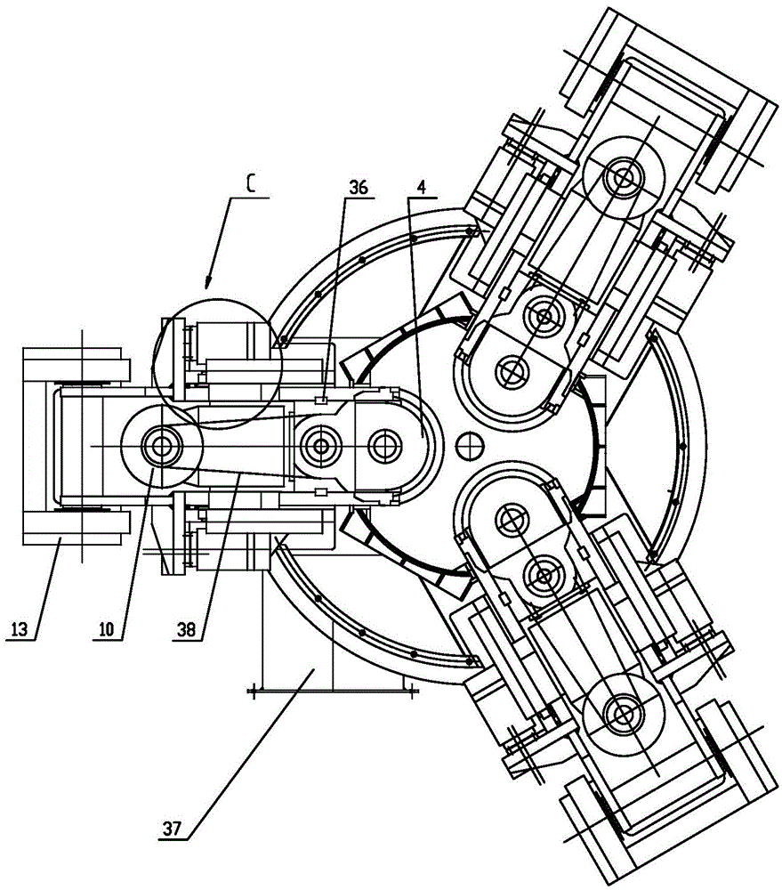
[0037] Such as Figure 1 to Figure 3 The present invention is composed of upper body 3, lower body 15 and base plate 16 to form a closed body. The upper end of the upper body 3 is connected to the classifier, and a feeding device consisting of a feeding screw 1 and a feeding pipe 2 is installed on the side. The periphery of the lower part of the upper body is radially and evenly distributed with three saddles 29, the top of the saddle 29 is provided with a step, the lower plane 53 of the step is fixedly equipped with a guide block 48, and the bottom of the swing arm body 33 is provided with two pairs of swing arm body rollers 34, The swing arm body roller 34 can slide in the groove formed by the step facade 52 and the guide block 48, on the guide block 48 top, a briquetting block 47 is arranged near the swing arm body roller 34 side, and the briquetting block 47 and the guide block 48 are together Constrains the movement direction of the swing arm body.

[0038]The front end...

Embodiment 2

[0052] The difference between this preferred embodiment and preferred embodiment 1 is that in this preferred embodiment, the number of grinding head bodies 4 is not limited, and it is necessary not to interfere between the equipment. The swing arm body roller 34 is arranged on the side of the swing arm body 33. Swing arm body roller 34 is three pairs, four pairs, five pairs or six pairs.

[0053] The specific working method is the same as that of the first preferred embodiment.


PUM


Abstract

The invention discloses a hydraulically-loaded dual-power pulverizer which comprises a body, a large pulverizing disc arranged in the body, a pulverizing disc power device for driving the large pulverizing disc, and pulverizing head bodies matched with the large pulverizing disc, wherein the pulverizing head bodies are arranged on saddles. The pulverizer also comprises a pulverizing head power mechanism for driving the pulverizing head bodies, a charging device arranged on the upper part of the body, and an air inlet system and an overflow recovery device which are arranged at the bottom of the body, wherein the front ends of swinging arm bodies are rigidly connected with the pulverizing head bodies through pin shafts, screws and fixing keys; pulverizing head rollers are pressed to the inner side of the steep wall of the outer edge of the large pulverizing disc under the action of hydraulic devices; the tail ends of the swinging arm bodies are connected with a tail frame through rotating wheel shafts, so that the swinging arm bodies can rotate around the rotating wheel shafts, respectively; lubricating oil circulation systems are used for pulverizing head spindles. The whole pulverizer can stably run, and is slight in vibration, easy to maintain and high in efficiency.

Description

technical field [0001] The invention relates to a micropowder vertical roller cutting mill, in particular to a hydraulic-loaded dual-power mill. Background technique [0002] The structure of the known mills is mostly that the large grinding disc rotates around the central axis, the central axis is driven by the lower motor and the reducer, the grinding head and grinding roller are driven by the large grinding disc to rotate around their own axis, and the grinding head and grinding roller have no power , when this vertical roller mill is working, the effect of the grinding roller and the large grinding disc on the material is mainly to grind the material into powder by extrusion. Chinese patent vertical roller mill, application number 02258005.0, is a spring-loaded dual-power grinding and milling equipment, including the body, the large grinding disc in the lower body and its power transmission mechanism, and two to five evenly distributed and large grinding discs. The grin...

Claims


Application Information

Patent Timeline
Patent Type & Authority Patents(China)
IPC IPC(8): B02C15/00B02C15/10
Inventor 伊启平朱纯王海青
Owner HAIAN TIANPENG MACHINERY MFG
Learn More