
Jig special for laser welding

A special fixture and laser welding technology, which is applied in laser welding equipment, welding equipment, welding equipment, etc., can solve the problems of affecting the access of protective gas, hindering filling, and large volume, and achieve the effect of facilitating the aggregation of light spots

Inactive Publication Date: 2014-05-21
HENAN UNIV OF SCI & TECH
View PDF6 Cites 3 Cited by
  • Summary
  • Abstract
  • Description
  • Claims
  • Application Information

AI Technical Summary

Problems solved by technology

[0003] In the process of laser welding, fixtures are often needed to clamp and fix the materials to be welded. There are many problems in the use of traditional laser welding fixtures. Because its cross-sectional shape is V-shaped, it is very difficult to clean the sundries in the shielding gas tank, which will affect the access of shielding gas; moreover, the shape of the splint of the traditional laser welding jig near the end of the shielding gas tank occupies a volume If it is too large, it will hinder the filling of the weld and affect the laser focus

Method used


Image

  • Jig special for laser welding

Examples


Embodiment Construction

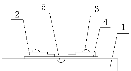
[0011] The specific implementation of the present invention will be described below in conjunction with the accompanying drawings. A special fixture for laser welding is provided with a base plate 1, and a shielding gas groove 5 with a circular arc-shaped cross section is provided on the base plate 1 for passing in Protective gas to obtain a protective atmosphere, its cross-section is set in a circular arc shape, which is convenient for cleaning the welding slag inside after long-term use. The substrate 1 is also provided with a splint 2 for fixing the material 4 to be welded on it, and the splint 2 passes through The fixing screw 3 is detachably fixed on the base plate 1. For this, threaded holes that can cooperate with the fixing screws can be provided on the splint 2 and the base plate 1 to facilitate the fixing and disassembly of the splint 2. The splint 2 on the base plate 1 should be provided with However, it should be noted that the end of the splint 2 close to the shiel...


PUM


Abstract

The invention relates to a jig for welding, in particular to a jig special for laser welding. The jig special for laser welding is provided with a base plate, a strip-shaped protective gas groove allowing protective gas to enter in order to obtain protective atmosphere in the welding process is formed in the base plate, clamping plates used for fixing materials to be welded to the base plate are arranged on the base plate, and the clamping plates are detachably fixed to the two sides of the protective gas groove. The cross section of the protective gas groove is in an arc shape, and one end, close to the protective gas groove, of each clamping plate is arranged in a step shape. Accordingly, impurities like accumulated welding slag in the protective gas groove due to long-term use can be cleared out easily, and the impurities can be cleared out through slight blowing or striking the base plate by enabling the protective gas groove to be erected. In addition, one end, close to the protective gas groove, of each clamping plate is arranged in the step shape, compared with a traditional laser welding jig, the jig special for laser welding has the advantages that padding on welding joints of the materials to be welded is further facilitated through the step-shaped clamping plates, and light spot gathering in the process of laser welding is facilitated.

Description

technical field [0001] The invention relates to a clamp for welding, in particular to a special clamp for laser welding. Background technique [0002] Laser welding is an efficient and precise welding method that uses a high-energy-density laser beam as a heat source. It is one of the important aspects of the application of laser material processing technology; laser welding was mainly used for welding thin-walled materials and low-speed welding in the 1970s. The welding process is a heat conduction type, that is, the laser radiation heats the surface of the workpiece, and the surface heat diffuses to the inside through heat conduction. By controlling the parameters such as the width, energy, peak power and repetition frequency of the laser pulse, the workpiece is melted and a specific molten pool is formed. Laser welding Due to its unique advantages, it has been successfully applied in the precision welding of micro and small parts. [0003] In the process of laser welding...

Claims


Application Information

Patent Timeline
Patent Type & Authority Applications(China)
IPC IPC(8): B23K26/70B23K26/142
CPCB23K26/702B23K37/0435
Inventor 王文焱张豪胤许开辉元亚莎谢敬佩王爱华王爱琴李继文李洛利
Owner HENAN UNIV OF SCI & TECH
Learn More