
Monitoring system for thermal error of machine tool spindle

A monitoring system, a thermal error technology, applied in measurement/indication equipment, metal processing mechanical parts, metal processing equipment, etc., can solve problems affecting fault detection, can not meet the high precision and real-time measurement requirements of thermal deformation measurement of machine tool spindles, temperature measurement Point wiring difficulties and other problems, to achieve the effect of fast response, wireless transmission and processing, and improved monitoring efficiency

Inactive Publication Date: 2014-05-21
NANTONG UNIVERSITY +1
View PDF5 Cites 17 Cited by
  • Summary
  • Abstract
  • Description
  • Claims
  • Application Information

AI Technical Summary

Problems solved by technology

At present, the temperature monitoring of machine tool spindles mostly uses wiring to install temperature sensors to obtain temperature signals, which makes it difficult to wire some important temperature measurement points under complex working conditions of machine tools, and also affects fault detection.
On the other hand, the thermal deformation monitoring of machine tool spindles mostly uses eddy current displacement sensors to collect displacement signals, which cannot meet the high-precision and real-time measurement requirements for thermal deformation measurement of machine tool spindles.

Method used


Image

  • Monitoring system for thermal error of machine tool spindle
  • Monitoring system for thermal error of machine tool spindle
  • Monitoring system for thermal error of machine tool spindle

Examples


Embodiment Construction

[0023] The present invention will be described in further detail below in conjunction with the accompanying drawings.

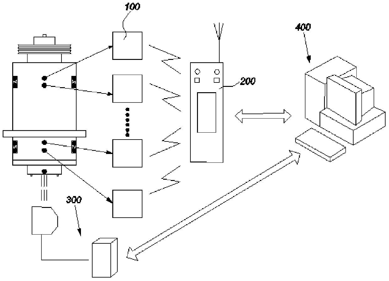
[0024] figure 1 A thermal error monitoring system for a machine tool spindle according to an embodiment of the present invention is schematically shown.

[0025] Such as figure 1 As shown, it is a vertical machining center spindle thermal error monitoring system, including a temperature sensing tag 100, an RFID reader 200, a laser displacement sensor testing system 300, a host computer control system 400, a temperature sensing tag 100 and an RFID reader 200 communicate wirelessly, the RFID reader 200 is connected to the host computer control system 400 through the RS232 serial port, and the laser displacement sensor test system 300 is connected to the host computer control system 400 through the USB serial port.

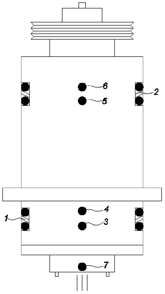
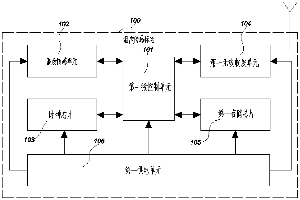
[0026] Such as figure 1 , 3 , 4, and 5, the temperature sensing label 100 includes a first micro control unit 101 (MSP430F149), a temperature s...


PUM


Abstract

The invention discloses a monitoring system for a thermal error of a machine tool spindle. The monitoring system for the thermal error of the machine tool spindle comprises temperature sensing tags, an RFID reader, a laser displacement sensor testing system and an upper computer control system, wherein the RFID reader and the laser displacement sensor testing system receive measuring instructions of the upper computer control system, the measuring instructions received by the RFID reader are output to the temperature sensing tags, information of the temperature measured by the temperature sensing tags is output to the RFID reader, and is transmitted to the upper computer control system, a laser displacement sensor control system outputs thermal deformation signals at the moment corresponding to the moment of obtaining of the information of the temperature to the upper computer control system, and the upper computer control system processes information of thermal deformation and the information of the temperature to obtain information of the thermal error. The monitoring system for the thermal error of the machine tool spindle is easy to operate, high in anti-interference capacity and high in response speed, online monitoring is carried out on the thermal error of the machine tool spindle, wireless transmission and processing of the information of the temperature and the information of thermal deformation are achieved, and monitoring efficiency of the thermal error of a machine tool is improved.

Description

technical field [0001] The invention relates to the field of dynamic measurement of the thermal error of the main shaft of a machine tool, in particular to a monitoring system for the thermal error of the main shaft of a machine tool. Background technique [0002] The thermal error of the machine tool spindle is mainly manifested in two aspects of temperature and thermal deformation. The error caused by the temperature rise and thermal deformation of the spindle is an important factor affecting the machining accuracy of the machine tool. At present, the temperature monitoring of machine tool spindles mostly adopts wiring to install temperature sensors to obtain temperature signals, which makes wiring difficult for some important temperature measurement points under complex working conditions of machine tools, and also affects fault detection. On the other hand, the thermal deformation monitoring of the machine tool spindle mostly uses eddy current displacement sensors to col...

Claims


Application Information

Patent Timeline
IPC IPC(8): B23Q17/00
CPCB23Q17/007
Inventor 袁江吕晶邱自学薛伯军居振华邵建新
Owner NANTONG UNIVERSITY
Learn More