A live welding compensation device under full current for aluminum electrolytic cell series

A live welding and aluminum electrolytic cell technology, which is applied in the field of aluminum electrolysis, can solve the problems of electrolytic production impact, cumbersome connection methods, and influence on welding quality and process, so as to avoid production impact and save installation and operation time.

Active Publication Date: 2016-04-13
GUIYANG AL-MG DESIGN & RES INST
View PDF4 Cites 0 Cited by
  • Summary
  • Abstract
  • Description
  • Claims
  • Application Information

AI Technical Summary

Problems solved by technology

In this invention, it is necessary to divide the overhaul electrolyzer into several areas first, and then set up multiple sets of cross-tank emergency busbars. One end of the cross-tank emergency busbar is connected to the anode busbar of the overhaul electrolyzer through the bow-shaped fixture and the balance busbar, and the other end is passed through the column door. Type clamps are used to connect the column bus bars of the downstream electrolyzers, which is relatively cumbersome
When welding different areas, it is necessary to disconnect the corresponding column busbar and short-circuit busbar at the bottom of the slot (the one that has the greatest impact on welding), and at the same time connect the cross-slot emergency busbars in other areas. This process is time-consuming and there is another problem: with the welding process The current in the cathode steel rod will change, but it is difficult to adjust at this time, that is, the current flowing through the cathode steel rod cannot be actively adjusted in time and dynamically during the welding process, which affects the quality and process of welding
In addition, although live welding can delay the cooling of molten aluminum, the uneven current for too long will affect the electrolytic production

Method used


Image

  • A live welding compensation device under full current for aluminum electrolytic cell series
  • A live welding compensation device under full current for aluminum electrolytic cell series
  • A live welding compensation device under full current for aluminum electrolytic cell series

Examples


Embodiment Construction

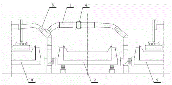
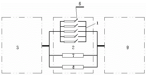
[0017] Such as image 3 As shown, aluminum electrolytic production consists of multiple electrolytic cells connected in series. Here, the electrolytic cell requiring live welding is defined as the overhaul electrolytic cell 2, the front-end electrolytic cell connected in series with it is the upstream electrolytic cell 9, and the rear end of the overhaul electrolytic cell 2 is connected in series. The electrolytic cell is defined as the downstream electrolytic cell 3, and in the overhaul electrolytic cell 2, from top to bottom, there are current drainage magnetic compensation device 1, cathode steel rod 7 and short-circuit busbar 8 at the bottom of the cell.

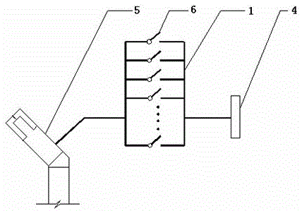
[0018] When welding the connecting plate of the cathode steel rod 7 of the aluminum electrolysis overhaul electrolytic cell 2, in order to reduce the magnetic field at the welding point, multiple sets of current-draining magnetic compensation devices 1 are installed, such as Figure 4 shown. One end is connected to the ...


PUM


Abstract

The invention discloses a current drainage compensating device with a variable resistance adjustment function when welding a cathode steel rod with electricity under the full current of a series of aluminum electrolytic cells. Drainage magnetic compensation device (1) acts as a draining conductor, connecting the anode busbar (4) of the overhaul electrolyzer (2) and the column busbar (5) of the downstream electrolyzer, so that part or all of the series current does not pass through the overhaul electrolyzer (2) It itself or the bottom of the tank short-circuits the busbar (8), but directly enters the downstream electrolytic tank (3) through the magnetic compensation device (1). One or more sets of current-carrying switches are set on the current-draining magnetic compensation device (1). By closing and opening the switches, the resistance of the current-draining magnetic compensation device (1) is changed to adjust its current flow, so as to achieve the purpose of controlling the magnetic field in the target area. , the invention shortens the welding operation time, simplifies the structure and process, and avoids the influence of welding on electrolytic production.

Description

technical field [0001] The invention relates to a welding equipment for cathode steel rods, soft strips and busbars under full current of electrolytic cell series, which belongs to the technical field of aluminum electrolysis. Background technique [0002] Aluminum electrolytic production consists of multiple electrolytic cells connected in series, using DC high current power supply, and the magnetic field strength generated by electrolytic cells with a capacity of 160kA-600kA is about 100-400Gs. Under this strong magnetic field, ordinary welding technology and equipment are used. Basically, steel-steel welding and aluminum-aluminum welding cannot be realized. At present, the connection between cathode steel bars and busbars of 160kA-600kA electrolyzers can only be welded by crimping technology or power failure and current reduction methods. [0003] However, the crimping method is used to realize the connection between the conductors. Compared with the welding method, the ...

Claims


Application Information

Patent Timeline
Patent Type & Authority Patents(China)
IPC IPC(8): C25C3/06C25C3/16C25C3/20C25C3/08B23K37/00
Inventor 黄俊杨涛王紫千
Owner GUIYANG AL-MG DESIGN & RES INST
Why Eureka
Try Eureka