

Distance measurement method for power distribution network single-phase earth fault on the basis of aerial mode traveling wave mutation
A single-phase ground fault, line-mode traveling wave mutation technology, applied in the fault location, using the pulse reflection method to detect faults and other directions, can solve the problems of ranging errors, false fault points, and high instability of the distribution network system, to achieve The effect of reducing random interference and improving accuracy
- Summary
- Abstract
- Description
- Claims
- Application Information
AI Technical Summary
Problems solved by technology
Method used
Image

Examples
Embodiment 1
[0044] A distance measurement method for a single-phase ground fault in a distribution network based on a line-mode traveling wave mutation, comprising the following steps:
[0045] (A) Simultaneously inject the same high-voltage pulse into the three phases at the head end of the distribution network, and detect the traveling voltage wave returned by the three phases; the injected high-voltage pulse is a high-voltage pulse with a pulse width of Xμs and an amplitude of YkV, such as image 3 , the voltage traveling wave of the three-phase return is detected;
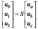
[0046] (B) Use the traveling wave of each phase voltage obtained in step (A) Transform the formula, transform the phase-mode transformation matrix to the modulus, and S adopt Karen Bower transformation or Clarke transformation matrix to obtain the line-mode voltage traveling wave;
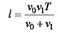
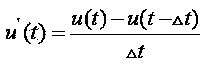
[0047] (C) Differentially deriving the traveling wave of the line-mode voltage obtained in step (B) to obtain the moment of the first non-ze...
Embodiment 2
[0066] Such as figure 1 As shown, this embodiment is an experiment of single-phase ground fault distance measurement in a distribution network, using the Frequency Dependent Models in PSCAD (Power Systems Computer Aided Design); figure 2 It is the structure diagram of the experimental circuit, A is the head end of the line (that is, the detection point), and the end of each branch is connected with a 10kV / 0.4kV distribution transformer (Dyn or Yyn connection) and a three-phase unbalanced load, and the sampling frequency is 10MHz. Setup failure occurs at figure 2 The EI section line from point E to point I has a grounding resistance of 100Ω and a distance of 17km from the head end.
[0067] First, a high-voltage pulse with a pulse width of 4μs and an amplitude of 10kV is injected into the three phases at the head end of the line at the same time to obtain the three-phase voltage traveling wave signal returned by the line, as shown in image 3 show; use right image 3 Th...
PUM
 Abstract
Description
Claims
Application Information