Solid-state rotational rate sensor device and method

a piezoelectric rate and sensor device technology, applied in the direction of acceleration measurement using interia force, speed measurement using gyroscopic effects, electric/magnetic means, etc., can solve the problem of less accuracy of vibrational motion control by single-ended actuators, responsive amplitude of secondary vibration, etc., to improve immunity and increase the overall device and system performance

Inactive Publication Date: 2006-02-16
TRIAD SENSORS
View PDF6 Cites 12 Cited by
  • Summary
  • Abstract
  • Description
  • Claims
  • Application Information

AI Technical Summary

Benefits of technology

[0010] In one embodiment, the present invention utilizes piezoelectric materials in a thin-film format. The thin-film distinction enables transducers with a far higher degree of complexity and accuracy. Thin-films offer the following key advantages:
[0011] Matching—Thin-film piezoelectric materials are deposited and defined on an atomic scale utilizing fabrication processes common in the semiconductor industry. The result is that thin-film piezoelectric elements can be consistently manufactured with element matching more than 100× better than conventional bulk machined devices.
[0013] Accuracy—In a thin-film format, piezoelectric materials exhibit reduced levels of random noise. At system level, the effect of lower noise is higher accuracy readings.
[0017] The present invention further provides differential piezoelectric elements for sensing and driving the vibrational motion of the rotational rate sensor. Differential elements provide improved immunity to temperature, vibration, package strain, electromagnetic interference and other undesirable effects that corrupt sensor data in existing rate sensor devices.
[0018] The present invention further provides a method for detecting the Coriolis force based on the phase shift between the secondary and primary vibrational motions in a vibrating rotational rate sensor. By measuring the phase shift of the rate sensor output signals, further immunity to temperature, vibration, package strain, electromagnetic interference and other undesirable effects is achieved.
[0019] The above advantages are inherent to the present invention and enable novel configurations and unique features that increase the overall device and system performance.

Problems solved by technology

However, in most of these examples, bulk piezoelectric material is machined and assembled in a coarse manner to achieve low-complexity devices.
However, the amplitude of secondary vibration is also responsive to temperature, vibration, package strain, electromagnetic interference and other undesirable effects that corrupt the rate sensor data.
Single-ended actuators provide less accuracy in controlling the vibrational motion.

Method used


Image

  • Solid-state rotational rate sensor device and method
  • Solid-state rotational rate sensor device and method
  • Solid-state rotational rate sensor device and method

Examples


Embodiment Construction

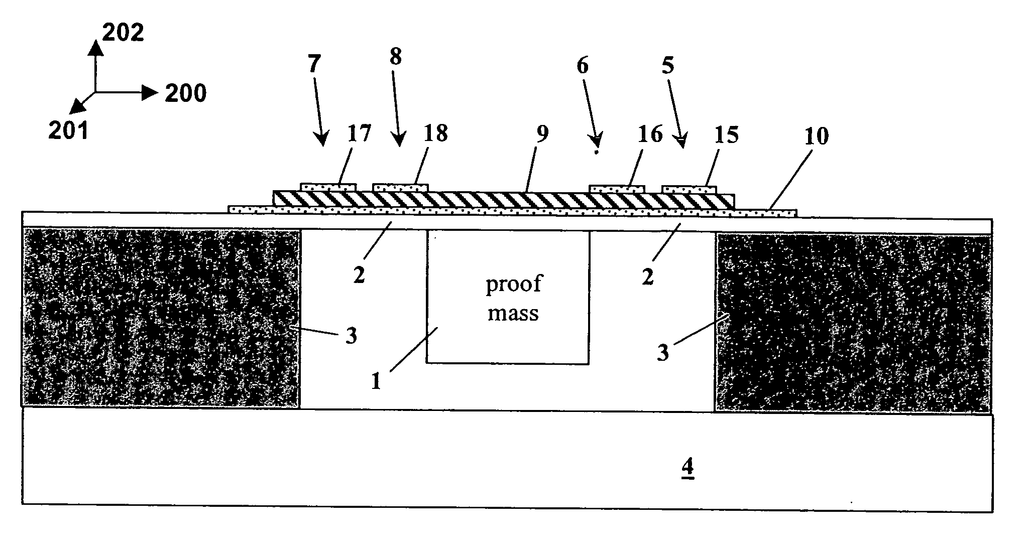
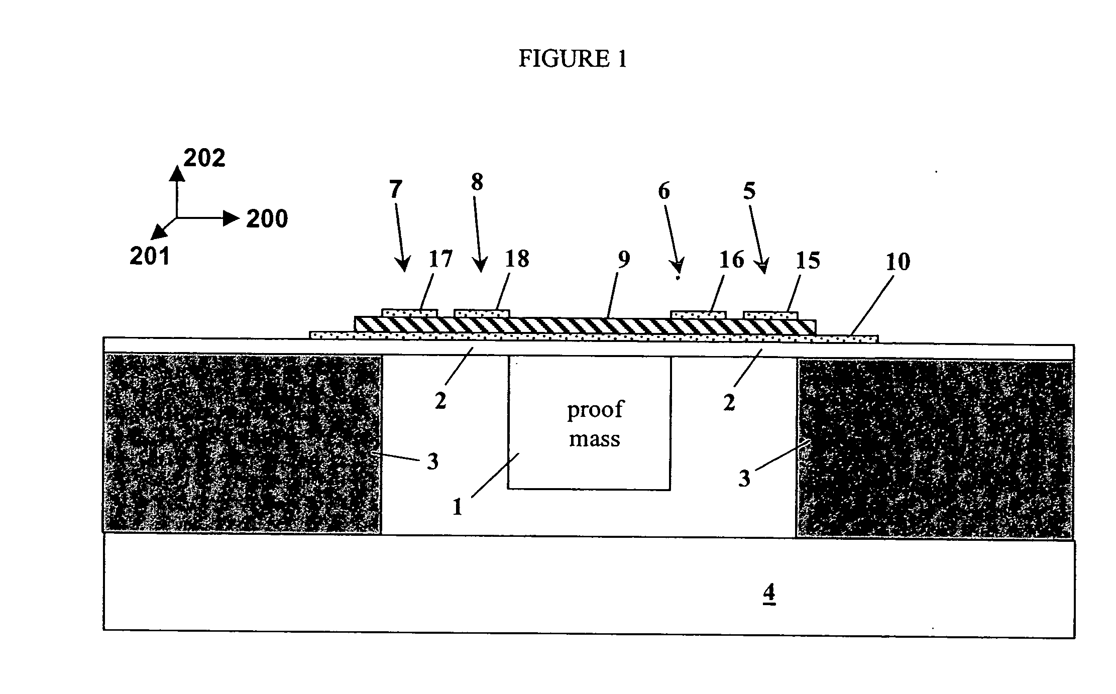
[0032] The present invention provides a solid-state rotational rate sensor device formed by thin films for generating an electrical signal output proportional to the rate of rotational motion. The precision thin-film piezoelectric elements are configured and arranged on a semi-rigid structure to detect rotation (such as pitch, roll, and yaw) while rejecting spurious noise created by vibration, thermal gradients, and electromagnetic interference.

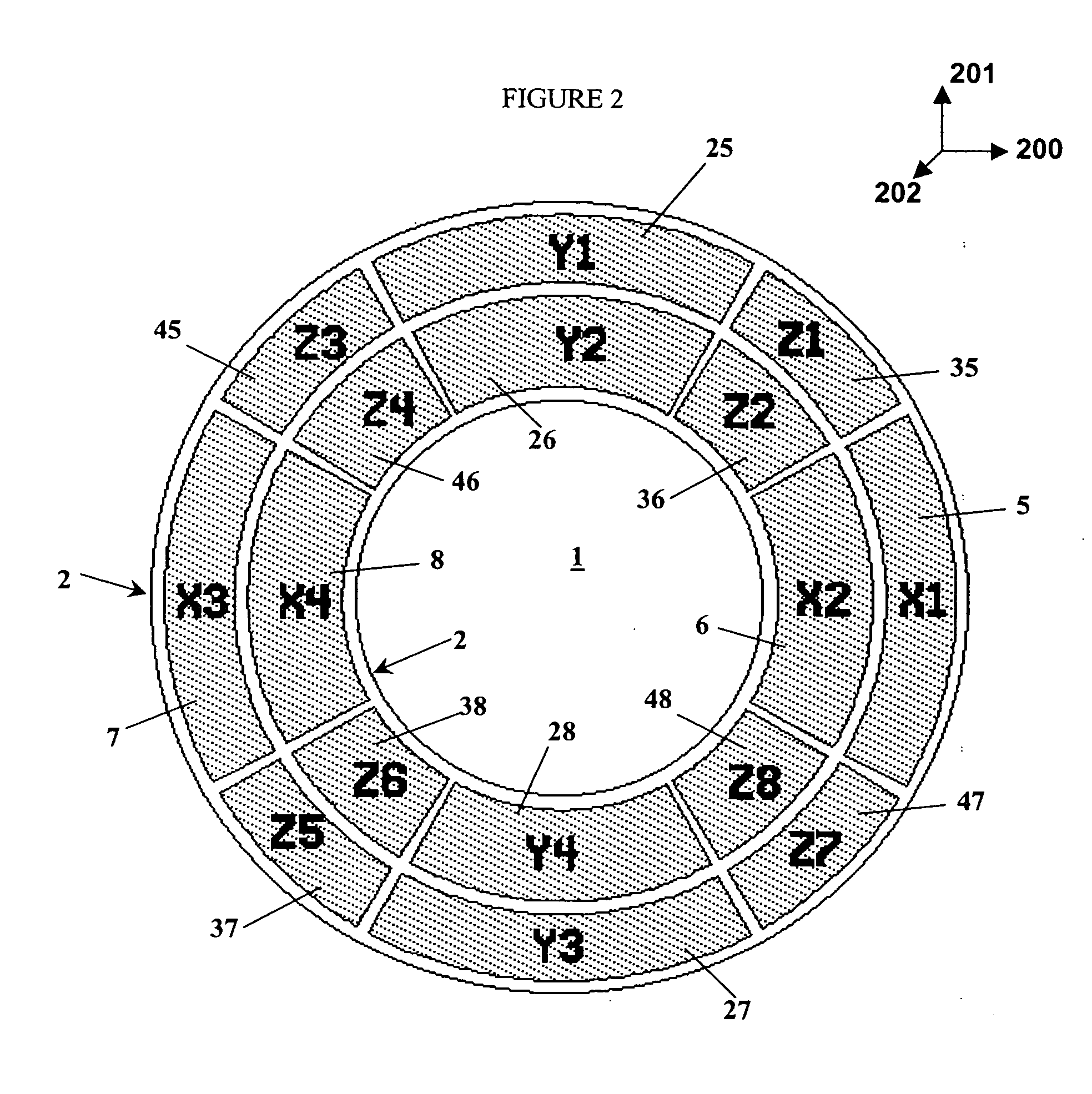
[0033] The main features of one embodiment of a rotational rate sensor device (also referred to as “gyro”) are shown in FIG. 1. The device includes a) a cylindrical silicon proof-mass 1 that is suspended on b) a toroidal thin-film membrane 2 on which are c) a series of thin-film piezoelectric elements 5, 6, 7, and 8. Typically, the height of the proof-mass 1 is about 500 microns, the diameter of the proof-mass 1 is about 400 microns, while the outer diameter of the membrane 2 toroid is about 700 microns. The membrane 2 can be realized with a...


PUM


Abstract

The present invention provides a solid-state rotational rate sensor device formed by a thin-film for generating an electrical voltage output proportional to the rate of rotational motion. The precision thin-film piezoelectric elements are configured and arranged on a semi-rigid structure to detect rotation (such as pitch, roll, and yaw) while rejecting spurious noise created by vibration, thermal gradients, and electromagnetic interference.

Description

CROSS-REFERENCE TO RELATED APPLICATION DATA [0001] The present utility patent application claims priority of U.S. Provisional Patent Application, Ser. No. 60 / 402,104, filed Aug. 8, 2002, subject matter of which is incorporated herewith by reference.FIELD OF THE INVENTION [0002] The present invention relates generally to a piezoelectric rate sensor device and method, and more particularly, to a solid-state piezoelectric rate sensor device and method for measuring the rate of rotational motion. BACKGROUND OF THE INVENTION [0003] Piezoelectric materials are used in a variety of sensors and actuators. Piezoelectric materials convert mechanical energy to electrical energy and vice versa. For instance, if pressure is applied to a piezoelectric crystal, an electrical signal is generated in proportion thereby producing the function of a sensor. Generation of an electrical signal in response to an applied force or pressure is known as the “primary piezoelectric effect”. Similarly, if an elec...

Claims


Application Information

Patent Timeline
Patent Type & Authority Applications(United States)
IPC IPC(8): G01P9/04G01C19/56
CPCG01C19/56
Inventor SCHILLER, PETER J.
Owner TRIAD SENSORS
Why Eureka
Try Eureka