Laser scanning method, device and imaging equipment

A laser scanning device and laser scanning technology, applied in the field of laser scanning, can solve the problem of low accuracy of laser scanning and achieve the effect of precise scanning

Active Publication Date: 2014-05-21
APEX MICROELECTRONICS CO LTD
View PDF7 Cites 5 Cited by
  • Summary
  • Abstract
  • Description
  • Claims
  • Application Information

AI Technical Summary

Problems solved by technology

[0005] The invention provides a laser scanning method, device and imaging equipment to solve the problem of low accuracy of laser scanning in the prior art

Method used


Image

  • Laser scanning method, device and imaging equipment
  • Laser scanning method, device and imaging equipment
  • Laser scanning method, device and imaging equipment

Examples


Embodiment Construction

[0030] In order to more clearly illustrate the technical solutions in the embodiments of the present invention or the prior art, the following will briefly introduce the drawings that need to be used in the description of the embodiments or the prior art. Obviously, the accompanying drawings in the following description These are some embodiments of the present invention. For those skilled in the art, other drawings can also be obtained according to these drawings without any creative effort.

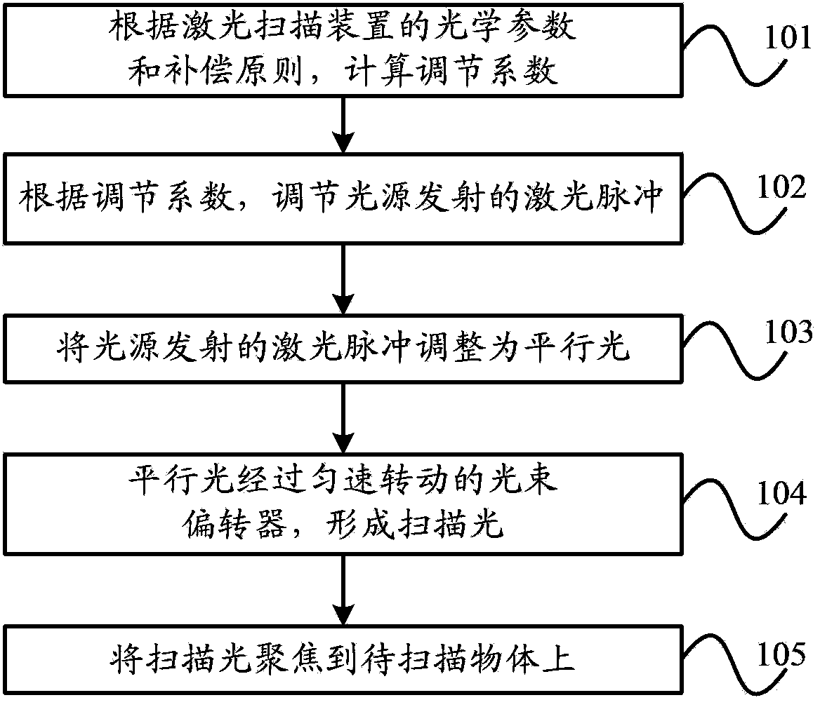
[0031] figure 2 It is a flow chart of Embodiment 1 of the laser scanning method of the present invention. Such as figure 2 As shown, the method of the present embodiment includes:

[0032] Step 101. Calculate the adjustment coefficient according to the optical parameters and compensation principles of the laser scanning device.

[0033]Specifically, the adjustment coefficient can be calculated by using the optical parameters and compensation principles of the laser scanning device,...


PUM


Abstract

The invention provides a laser scanning method, a device and imaging equipment. The laser scanning method comprises steps that: adjusting coefficients are calculated according to optics parameters and a compensation principle of a laser scanning device; laser pulses emitted by a light source are adjusted according to the adjusting coefficients; the laser pulses emitted by the light source are adjusted to be parallel light; the parallel light is turned to be scanning light through a light beam deflector which uniformly rotates; the scanning light is focused on a scanned object. According to the method, the light source is adjusted through the adjusting coefficients, so light spots gathered on the object to be scanned have uniform consistency, and thereby accurate scanning for the scanned object can be realized.

Description

technical field [0001] The present invention relates to laser scanning technology, in particular to a laser scanning method, device and imaging equipment. Background technique [0002] Laser scanning technology is indispensable in the fields of printing imaging, graphic copying, laser coding and medical imaging. [0003] The specification of Chinese patent application No. 200610013649.2 discloses a common laser scanning device, figure 1 It is a structural schematic diagram of a laser scanning device in the prior art. Such as figure 1 As shown, the laser scanning device includes: a lens 1 , a lens 2 , a beam deflector 3 , a collimator lens 4 , and a light source 5 . Wherein, the light source 5 emits laser light with the same pulse duration and the same power. Lens 1 and Lens 2 constitute a scanning lens F-θ mirror. The beam deflector 3 is a hexaprism with 6 reflective surfaces. The beam deflector 3 rotates at a constant speed, so as to reflect the laser light emitted by...

Claims


Application Information

Patent Timeline
Patent Type & Authority Applications(China)
IPC IPC(8): G02B26/10G02B27/09
CPCG02B26/127G03G15/0435
Inventor 丁励孙万里宋丰君
Owner APEX MICROELECTRONICS CO LTD
Why Eureka
Try Eureka