
Solar cell and assembly and manufacturing method thereof

A technology for solar cells and batteries, applied in the field of solar cells, can solve the problems of hot spots of battery current, unsightly appearance, broken grids, etc., and achieve the effects of reducing the use of materials, avoiding damage, and reducing costs

Active Publication Date: 2014-05-21
HENGSHUI YINGLI NEW ENERGY
View PDF5 Cites 3 Cited by
  • Summary
  • Abstract
  • Description
  • Claims
  • Application Information

AI Technical Summary

Problems solved by technology

There are thin grid lines exposed on the front of the solar cell. During the production and printing process, grid breaks often occur, resulting in hot spots on the battery current (black spots appear in the EL test), and it is not beautiful enough.

Method used


Image

  • Solar cell and assembly and manufacturing method thereof
  • Solar cell and assembly and manufacturing method thereof
  • Solar cell and assembly and manufacturing method thereof

Examples


Embodiment 1

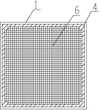
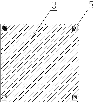
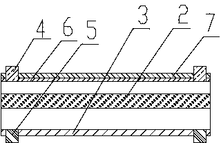
[0039] Such as Figure 1-3 As shown, a solar cell includes a battery body 1, the battery body 1 includes a battery PN junction part 2 and a back electric field part 3, a front electrode 4 and a grid line 6 are arranged on the front side of the battery body 1, and the The back of the battery body 1 is provided with a back electrode 5, the front electrode 4 is located on the edge of the upper surface of the battery body 1, the front electrode 4 is a long strip, there are four, and the front electrodes 4 are sequentially connected end to end to form a frame shape , the grid lines 6 are provided with a plurality of cross-connected ones, the grid lines 6 are located inside the frame structure surrounded by the front electrodes 4, and the two ends of the grid lines are respectively connected to the front electrodes. Preferably, the grid lines 6 are connected to each other in a cross, the front electrodes 4 are electrically connected to the grid lines 6, and there are four rear elect...

Embodiment 2

[0044] Such as Figure 4 As shown, the difference between this embodiment and the first embodiment lies in the structure of the front electrode, and other features are the same. In this embodiment, the front electrode 4 is square, and there are four pieces, which are respectively located at the four corners of the upper surface of the battery body 1. The grid lines 6 include thick grid lines 61 and thin grid lines 62. The thick grid lines The width of 61 is half of the width of the front electrode 4 , the front electrode 4 is connected by the thick grid line 61 , and the thin grid line 62 is located inside the frame structure formed by the front electrode 4 and the thick grid line 61 . Electrodes or thick grid lines are distributed around the battery sheet, which is conducive to the collection of charges around the edge of the battery sheet (the cross-section of the pn junction), which can greatly reduce leakage current and improve battery life.

[0045] The manufacturing met...


PUM


Abstract

The invention discloses a solar cell and assembly and a manufacturing method thereof and relates to the technical field of solar cells. The solar cell comprises a cell body, and the cell body comprises a cell PN junction portion and a back field portion. The solar cell is characterized in that the front surface of the cell body is provided with front surface electrodes and grid wires, the back surface of the cell body is provided with back electrodes, wherein the four front surface electrodes are arranged on the four corners or four edges of the top surface of the cell body, the grid wires are connected is a mutually crossed mode, the front surface electrodes are electrically connected with the grid wires, and the four back surface electrodes are arranged on the four corners and the four edges of the bottom surface of the cell body. The assembly manufactured from the solar cell can be welded in any directions for usage, avoid heat spots due to grid breakage, achieve good oxidation resistance, improve resistance to PID (potential induced decay), reduce leakage current, and be high in utilization rate, convenient to use and low in cost.

Description

technical field [0001] The invention relates to the technical field of solar cells, in particular to a solar cell, a manufacturing method thereof, and a solar cell component composed of the solar cell. Background technique [0002] Solar cells are products that convert solar energy into electrical energy and are the main components of photovoltaic modules. In order to ensure the absorption of sunlight and the high efficiency of current extraction, the metal wires of the network structure formed on the front side of the solar cell (facing the sun) are called grid lines, which are generally divided into main grid lines and thin grid lines. The back side of the solar cell (the side facing away from the sun) forms a back electric field in order to fully draw out the current. At the same time, for the convenience of welding, a metal back electrode is printed on the back electric field, which generally corresponds to the same number of main grid lines. [0003] Plasma-enhanced ch...

Claims


Application Information

Patent Timeline
Patent Type & Authority Applications(China)
IPC IPC(8): H01L31/0224H01L31/042H01L31/18
CPCH01L31/022425H01L31/188Y02E10/50Y02P70/50
Inventor 高艳杰
Owner HENGSHUI YINGLI NEW ENERGY
Learn More