Image pickup apparatus and filter

A camera device and optical filter technology, applied to signal generators, instruments, optics, etc. with a single pick-up device, can solve problems such as photoelectric conversion element saturation and image quality degradation

Inactive Publication Date: 2014-05-21
SONY CORP
View PDF10 Cites 5 Cited by
  • Summary
  • Abstract
  • Description
  • Claims
  • Application Information

AI Technical Summary

Problems solved by technology

Therefore, when infrared light is to be sufficiently detected, there is a problem that the photoele

Method used


Image

  • Image pickup apparatus and filter
  • Image pickup apparatus and filter
  • Image pickup apparatus and filter

Examples


example 5

[0032] 6. Example 5 (camera according to the present invention and filter according to mode 2 of the present invention)

[0033] 7. Example 6 (modified example of Example 5)

[0034] 8. Example 7 (another modified example of Example 5)

[0035] 9. Example 8 (Modifications of Example 1 to Example 7)

[0036] 10. Example 9 (Modifications of Example 1 to Example 8), and others

[0037] Overall illustration of the camera device according to the invention and the filters of mode 1 and mode 2 according to the invention

[0038] When the optical element in the imaging device according to the present invention is constituted by an optical filter, or in the case of an optical filter according to Mode 1 or Mode 2 of the present invention, the optical filter may be formed from an optical filter substrate and a The layer of filter material on the filter substrate constitutes, or the filter material may, for example, be kneaded or dispersed in the filter substrate. In the former case, ...

example 1

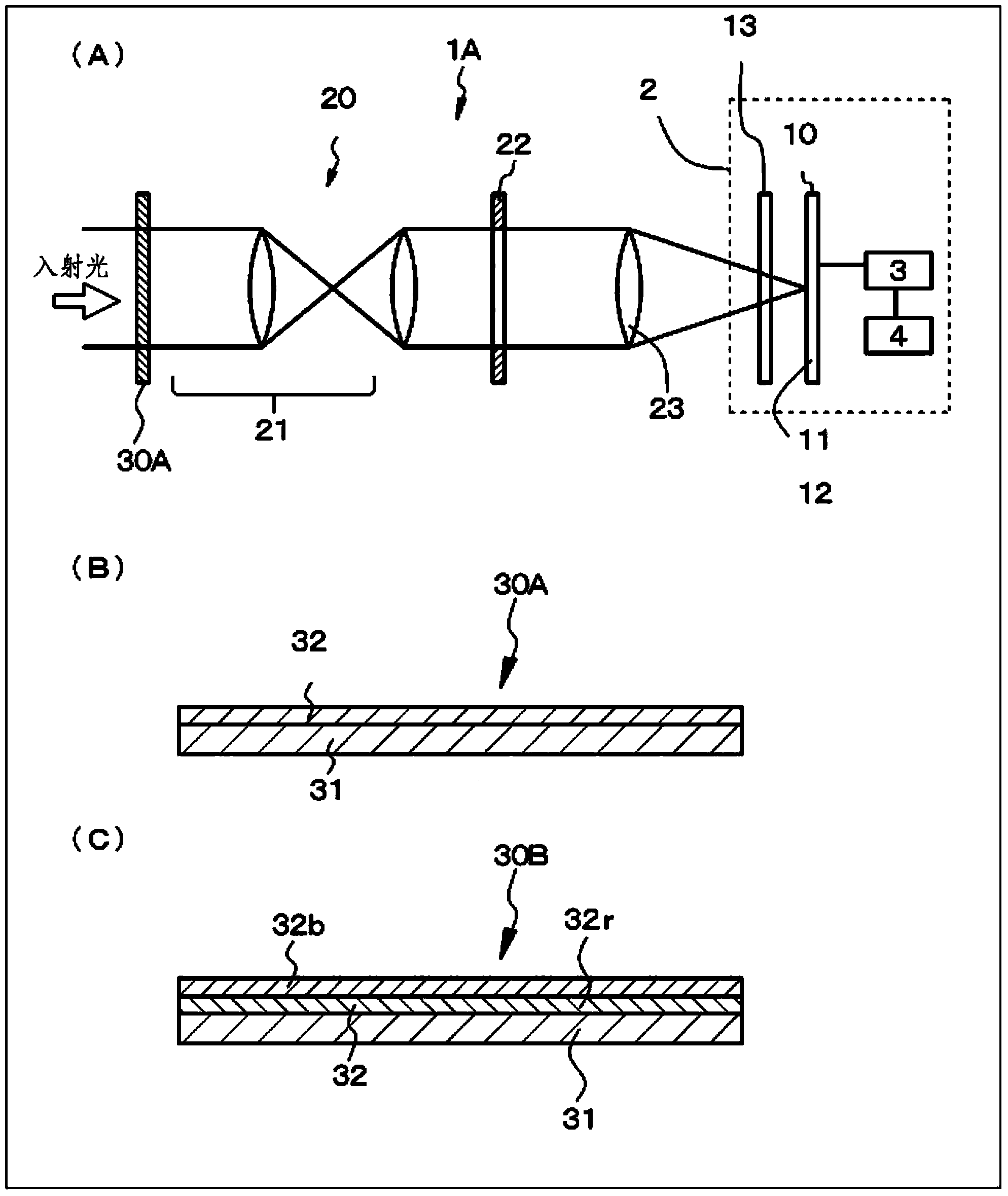
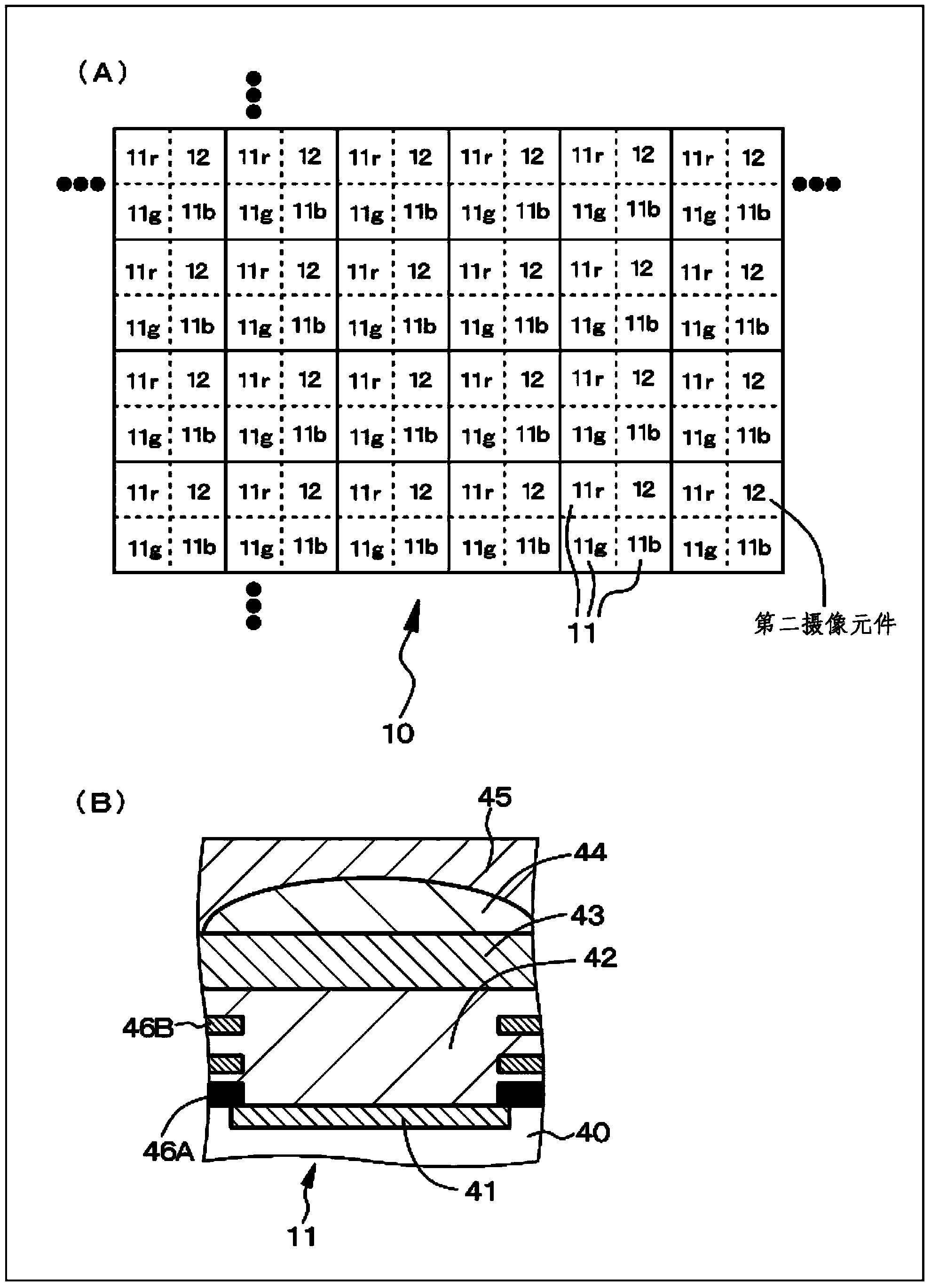
[0060] Example 1 relates to the imaging device according to the present invention, and more specifically, Example 1 relates to the imaging device A according to the present invention and the optical filter of Mode 2 according to the present invention. figure 1 (A) is a schematic diagram of an imaging device according to Example 1. figure 1 (B) is a schematic sectional view showing the filter according to Example 1 (optical element). also, figure 2 (A) schematically shows the arrangement of imaging elements in the imaging unit. figure 2 (B) is a schematic partial cross-sectional view showing the first imaging element.

[0061] An imaging device 1A according to Example 1 or imaging devices according to Examples 2 to 9 described later includes a lens system 20 and an imaging unit (imaging element array unit) 10 in which light that has passed through the lens system 20 is incident to the imaging unit 10 superior. An image pickup unit (image pickup element array unit) 10 in...

example 2

[0072] Example 2 is a modified example of Example 1. In Example 1, the filter material layer 32 is composed of a single layer. On the other hand, in Example 2, as shown a schematic sectional view figure 1As shown in (C), the filter 30B is fabricated by stacking a red transmissive layer 32r for transmitting red and a blue transmissive layer 32b for transmitting blue. More specifically, the red transmission layer 32r is composed of the same red filter material as the color filter for transmitting red and provided above the photoelectric conversion element of the imaging element. The blue transmission layer 32b is composed of the same blue filter material as the color filter for transmitting blue and provided above the photoelectric conversion element of the imaging element. The thicknesses of the red transmissive layer 32r and the blue transmissive layer 32b may be determined based on the relationship between the thickness of the red transmissive layer and the light transmitt...


PUM


Abstract

The present technology relates to an image pickup apparatus and a filter, said technology being capable of providing an image pickup apparatus that can detect infrared light or ultraviolet light and visible light in a same manner. An image pickup apparatus 1A is provided with a lens system 20, and an image pickup unit 10 having inputted thereto light that has passed through the lens system 20. The image pickup unit 10 has a plurality of first image pickup elements 11, which receive light in a first wavelength band; and a plurality of second image pickup elements 12, which receive light in a second wavelength band different from the first wavelength band. The lens system 20 or the image pickup unit 10 is provided with an optical element 30A, which makes the light in the first wavelength band reach the image pickup unit, said light having a light quantity smaller than that of the light in the second wavelength band.

Description

technical field [0001] The present invention relates to an imaging device and an optical filter. Background technique [0002] A single-plate color solid-state imaging device such as a CCD image sensor and a CMOS image sensor has an imaging element composed of a photoelectric conversion element and a color filter arranged above the photoelectric conversion element and for making red , green or blue through. In order to obtain information on a color video image, visible light passed through a color filter and received by a photoelectric conversion element is output as a signal by the photoelectric conversion element. On the other hand, in recent years, a single-plate color solid-state imaging device for detecting infrared light, which is a component other than visible light, has been developed (for example, see Japanese Patent Document JP2008-091753A). Attention is being paid to new applications that cannot be achieved by detecting visible light alone. More specifically, f...

Claims


Application Information

Patent Timeline
IPC IPC(8): H04N9/07H01L27/14
CPCG02B5/208H01L27/14621H04N23/11H04N25/131H04N25/135H04N25/134
Inventor 东堤良仁茂木英昭小泽谦岩间纯
Owner SONY CORP
Why Eureka
Try Eureka