A movable power transmission device for high-voltage test bus

A power transmission device, high-voltage test technology, applied in the direction of measuring device, transportation and packaging, measuring device casing, etc., can solve the problems of complicated connection mode of high-voltage equipment, low utilization rate of test equipment, low work efficiency, etc., to reduce high-voltage Effect of corona discharge, improvement of reliability and safety, and improvement of work efficiency

Active Publication Date: 2015-10-28
STATE GRID CORP OF CHINA +1
View PDF7 Cites 0 Cited by
  • Summary
  • Abstract
  • Description
  • Claims
  • Application Information

AI Technical Summary

Problems solved by technology

[0005] In order to solve the test and inspection work of various types and models of high-voltage equipment in the power system in the prior art, the present invention uses the bus bar as the connecting wire, and the height of the bus bar needs to be continuously adjusted when changing the tested product. It also needs to be connected with a step-up transformer, and the connection method of high-voltage equipment is relatively complicated. Every time the test conditions or the equipment under test are changed, a large amount of repetitive work will be faced, resulting in the problems of low utilization rate of test equipment, high labor intensity and low work efficiency. Then a kind of active power transmission device for high voltage test busbar is proposed

Method used


Image

  • A movable power transmission device for high-voltage test bus
  • A movable power transmission device for high-voltage test bus
  • A movable power transmission device for high-voltage test bus

Examples


specific Embodiment approach 1

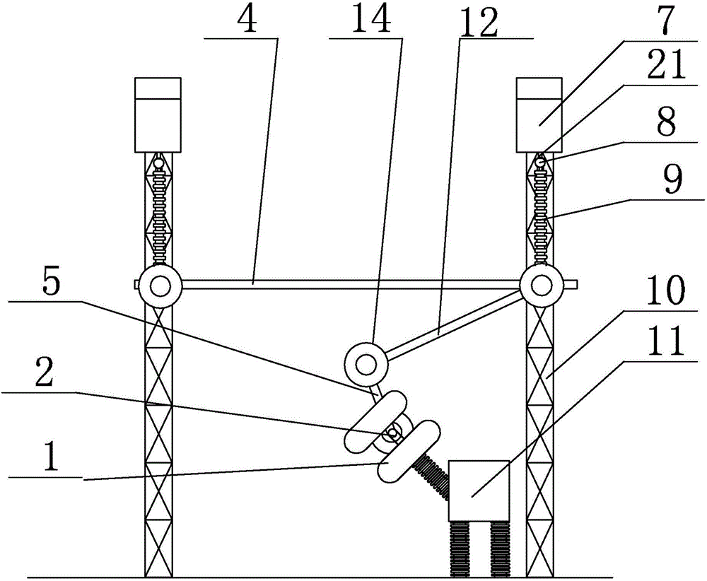
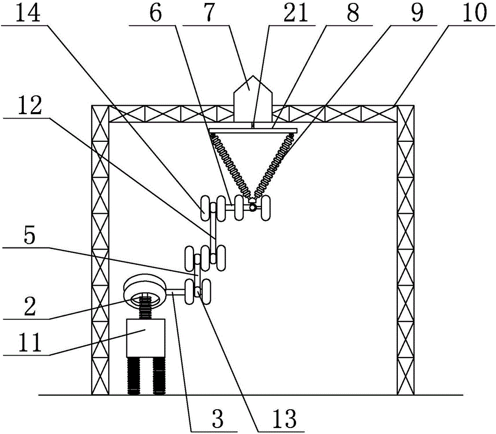
[0009] Specific implementation mode one: combine Figure 1-Figure 3 Describe this embodiment, a kind of movable power transmission device for high-voltage test busbar described in this embodiment, said device includes busbar 4, step-up transformer 11 and step-up transformer connector 2, and said device includes conductive connection mechanism, fixing mechanism and two lifting mechanisms, the fixed mechanism includes two gantry frames 10, the lifting mechanism includes a hoist 7, a hanger beam 8, two cables 21 and two insulators 9, the hanger beam 8 is a long rod body, and the two gantry frames 10 are arranged side by side Fixedly installed on the ground, a winch 7 is fixedly installed on the beam at the top of each gantry 10, and each winch 7 is fixedly connected with the middle part of the hanger beam 8 through a cable 21, and the two ends of each hanger beam 8 are respectively It is fixedly connected with one end of an insulator 9, and the other end of the insulator 9 is fix...

specific Embodiment approach 2

[0010] Specific implementation mode two: combination figure 1 and figure 2 Describe this embodiment, the active power transmission device for high-voltage test bus described in this embodiment, the conductive connection mechanism includes the first step-up transformer equalizing ring 1, the first connecting rod 3, the first movable connecting rod 5, The second connecting rod 6, the second movable connecting rod 12, four first sliding connectors 13 and a plurality of first pressure equalizing rings 14, the two ends of the first movable connecting rod 5 are respectively fixedly installed with a first sliding connector 13. A first sliding connector 13 is fixedly installed at both ends of the second movable connecting rod 12, three first pressure equalizing rings 14 are arranged side by side, and one end of the first movable connecting rod 5 is arranged between two adjacent first Between the pressure equalizing rings 14, one end of the second movable connecting rod 12 is arrange...

specific Embodiment approach 3

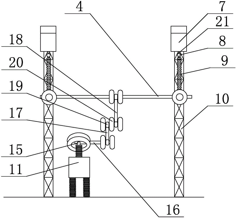
[0011] Specific implementation mode three: combination figure 1 and image 3 Describe this embodiment, the active power transmission device for high-voltage test bus described in this embodiment, the conductive connection mechanism includes the second step-up transformer equalizing ring 15, the third connecting rod 16, the third movable connecting rod 17, The fourth movable connecting rod 18, four second sliding connectors 19 and a plurality of second equalizing rings 20, the second step-up transformer equalizing ring 15 is fixedly installed on the step-up transformer connector 2, the third connecting rod 16 A second sliding connector 19 is respectively installed at both ends of the fourth movable connecting rod 18, and a second sliding connector 19 is respectively installed at both ends of the fourth movable connecting rod 18. Three second pressure equalizing rings 20 are arranged side by side, and the third movable connecting rod One end of 17 is arranged between two adjace...


PUM


Abstract

The invention discloses a bus movable power transmission device, relates to a power transmission device and aims at solving the problems of low utilization rate of test devices, great labor strength and low working efficiency caused due to a large quantity of repeated work when changing test conditions or tested devices for each time since a bus serves as a connection guide wire when testing and checking various types and various models of high-voltage devices of a power system in the prior art, the height of the bus needs to be adjusted continuously when replacing the tested articles, the bus also needs to be connected with a boosting transformer before testing for each time, and the connection manner of the high-voltage devices is complicated. The device comprises a bus, a boosting transformer, a boosting transformer connector, a transmission connection mechanism, a fixing mechanism and two lifting mechanisms, wherein the fixing mechanism comprises two portal frames; the lifting mechanisms comprise winches, lifting frame cross beams, two cable ropes and two insulators. The bus movable power transmission device is applicable to high-voltage test of a power system.

Description

technical field [0001] The invention relates to a power transmission device, in particular to a movable power transmission device for a high-voltage test bus. Background technique [0002] At present, with the increasing demand for long-distance power transmission, the voltage level of the power system continues to increase. The testing and inspection work of various types and models of high-voltage equipment in the prior art is becoming more and more heavy. Due to the high-voltage electrical equipment, especially the various instruments and equipment in the power system, there are many types and various models. Therefore, higher requirements are put forward for the test equipment in terms of the test efficiency and test capability of the test equipment. [0003] The bus bar is a kind of electrical equipment responsible for the transmission and distribution of electrical energy in the power supply system. After the electric energy is introduced into the substation, it is ...

Claims


Application Information

Patent Timeline
Patent Type & Authority Patents(China)
IPC IPC(8): B66C17/06G01R31/00G01R1/04
Inventor 刘洋鲁钢于春来朱学成
Owner STATE GRID CORP OF CHINA
Why Eureka
Try Eureka