
A high-pressure water jet auxiliary cutting head for roadheader

A technology of high-pressure water jet and cutting head, which is applied in the direction of cutting machinery, earthwork drilling and mining, etc., and can solve the problems of low efficiency of roadheaders and other problems

Inactive Publication Date: 2016-08-17
CHINA UNIV OF MINING & TECH
View PDF7 Cites 1 Cited by
  • Summary
  • Abstract
  • Description
  • Claims
  • Application Information

AI Technical Summary

Problems solved by technology

[0003] Technical problem to be solved: Aiming at the deficiencies of the prior art, the present invention proposes a high-pressure water jet auxiliary cutting head of the roadheader, which can effectively solve the problem of small and medium-sized power roadheaders in the prior art without the cost of increasing the power to cause tool wear. technical inefficiencies

Method used


Image

  • A high-pressure water jet auxiliary cutting head for roadheader
  • A high-pressure water jet auxiliary cutting head for roadheader
  • A high-pressure water jet auxiliary cutting head for roadheader

Examples


Embodiment 1

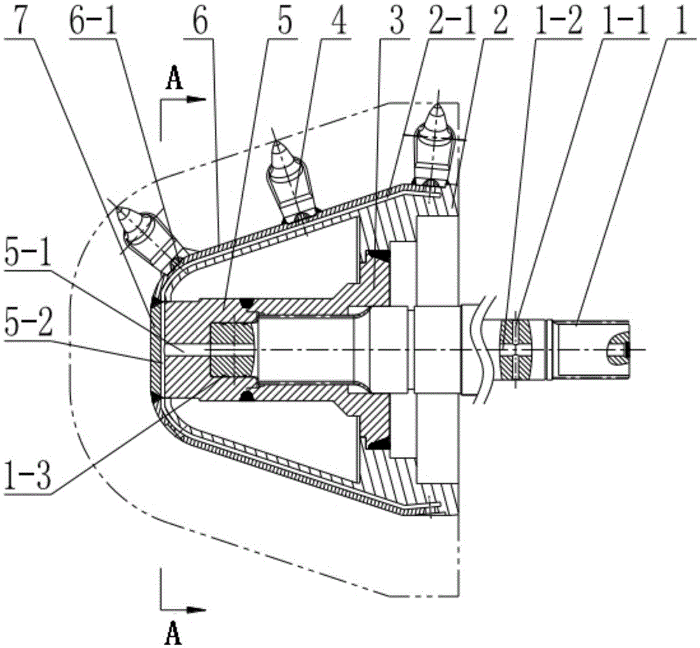
[0025] Such as Figure 1 to Figure 3 As shown, the roadheader high-pressure water jet auxiliary cutting head of the present invention includes a cutting shaft 1, a cone body 2, a core sleeve 3, a pick assembly 4, a core head 5, a cone cover plate 6, and a core head cover plate 7. The cone 2, the core sleeve 3, the pick assembly 4, the core head 5, the cone cover plate 6 and the core head cover plate 7 are all connected by welding, and the cutting shaft 1 is connected to the core sleeve through a spline 3 are connected to drive the whole cutting head to work, and a sealing ring 1-3 is arranged between the cutting shaft 1 and the core head 5.

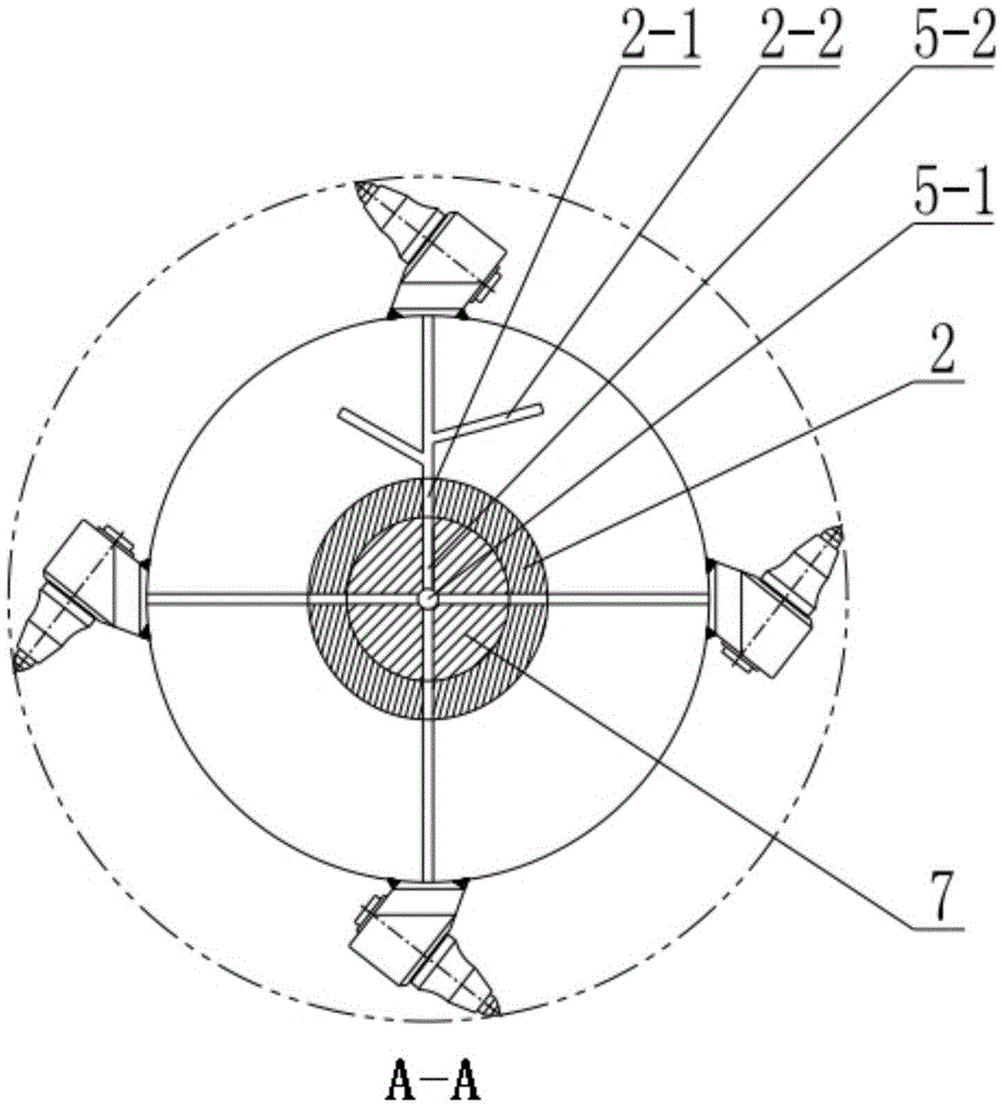
[0026] Cutting shaft 1 is provided with water inlet hole 1-1 and main flow channel 1-2, core head 5 is provided with core head main flow channel 5-1 and four core head branch flow channels 5-2, four core head branch flow channels 5 -2 is evenly arranged along the circumference of the core head 5, and the cone 2 is provided with four cone...

Embodiment 2

[0030] Such as figure 1 and Figure 4 As shown, the high-pressure water jet auxiliary cutting head of the roadheader of the present invention includes a cutting shaft 1, a cone body 2, a core sleeve 3, a pick assembly 4, a core head 5, and a high-pressure hose 8, and the cone body 2 , the core sleeve 3, the pick assembly 4, and the core head 5 are all connected by welding. The cutting shaft 1 is connected with the core sleeve 3 through a spline to drive the entire cutting head to work. The connection between the cutting shaft 1 and the core head 5 A sealing ring 1-3 is provided between them.

[0031] Cutting shaft 1 is provided with water inlet hole 1-1, main channel 1-2 and water outlet hole 1-4, cone 2 is provided with bolt hole type cone flow channel 2-3, core head 5 is provided with threaded hole type core head flow channel 5-3, the water outlet hole 1-4 is connected to the main channel and the threaded hole type core head flow channel 5-3, and the high pressure hose 8 i...

Embodiment 3

[0035] Such as figure 1 and Figure 5 As shown, the high-pressure water jet auxiliary cutting head of the roadheader of the present invention includes a cutting shaft 1, a cone body 2, a core sleeve 3, a pick assembly 4, a core head 5, and the cone body 2, the core sleeve 3, The pick assembly 4 and the core head 5 are all connected by welding. The cutting shaft 1 is connected with the core sleeve 3 through a spline to drive the entire cutting head to work. There is a sealing ring between the cutting shaft 1 and the core head 5. One 1-3.

[0036] Cutting shaft 1 is provided with water inlet hole 1-1, main channel 1-2 and water outlet hole 1-4, cone 2 is a solid cone, and is provided with cone flow channel 2-4, core head 5 is provided with The core flow channel 5-4, the water outlet 1-4 is connected to the main channel 1-2 and the core flow channel 5-4.

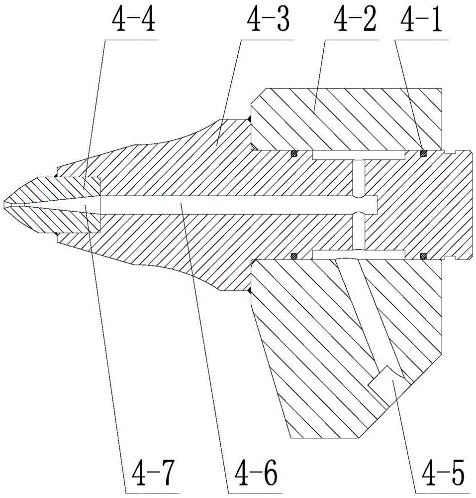
[0037] Pick assembly 4 mainly comprises tooth seat 4-2, tooth body 4-3 and tooth point 4-4, is provided with tooth seat fl...


PUM


Abstract

The invention discloses a heading machine cutting head assisted by high-pressure water jet. The cutting head comprises a cutting shaft, a cone, a core sleeve, a cutting pick assembly, and a core head; the cone is sleevedly connected to the periphery of the core head and the core sleeve; the cutting shaft is sleevedly arranged in the inner cavity of the core sleeve, and is inserted into a matched inner cavity in the inner of the core head so as to drive the cutting head to move; a pick seat runner, a pick body runner and a nozzle are arranged in the cutting pick assembly; the cutting shaft is provided with a water inlet hole and a main runner, one end of the water inlet hole is connected to a high-pressure water source, the other end of the water inlet hole is connected to the main runner; the core head is provided with a core head runner, and the cone is provided with a cone runner. The high-pressure water is introduced into the cutting head through the water inlet hole, then orderly flows through the core head runner and the cone runner, and finally flows into the cutting grid assembly; in the cutting grid assembly, the high-pressure water orderly flows through the grid seat runner and the grid body runner, and finally flows into the nozzle so as to form a high-pressure water jet which assists the cutting head to break rocks. The cutting head has a shape as the common cutting heads, so the cutting head can be applied to the cutting mechanism of heading machines in the same type, and thus has a wide application range.

Description

technical field [0001] The invention relates to the field of coal mines, mines and tunnel engineering equipment, in particular to a high-pressure water jet auxiliary cutting head on a boring machine. Background technique [0002] With the development of mechanized tunneling technology in coal mine underground tunnels, the constantly updated mechanized tunneling tools still cannot meet the needs of production. The excavation efficiency of the small power roadheader used in the excavation of thin coal seams, semi-coal rocks, gangue and small fault coal rocks is low, but the method of increasing power to solve the above existing problems will inevitably cause Tool wear is serious and there are potential safety hazards. Based on this, it is urgent to develop a high-pressure water jet auxiliary cutting head for roadheaders. At present, the design of the flow path of the cutting head of the roadheader leaves a water chamber to facilitate the spraying of low-pressure water through...

Claims


Application Information

Patent Timeline
Patent Type & Authority Patents(China)
IPC IPC(8): E21C25/60E21C35/187
Inventor 刘送永杜长龙朱真才江红祥彭玉兴沈刚李伟唐玮李洪盛周方跃胡修坤
Owner CHINA UNIV OF MINING & TECH
Learn More