Movable photovoltaic wave power generation ship

A wave power generation ship and mobile technology, applied in the field of mobile photovoltaic wave power generation ships, can solve the problems of low wave energy efficiency, many hydraulic parts, unsolved safety and service life of offshore power generation devices, etc., so as to improve power generation efficiency , Solve the effect of low efficiency and beneficial to grid connection

Inactive Publication Date: 2014-05-28
厦门中泰风电能源有限公司
View PDF8 Cites 11 Cited by
  • Summary
  • Abstract
  • Description
  • Claims
  • Application Information

AI Technical Summary

Problems solved by technology

[0003] At present, the common power generation technologies at sea mainly include wave power generation, tidal power generation, offshore wind power generation, ocean current power generation, and offshore solar power generation. However, the current utilization of marine energy is basically the development and utilization of a single form of energy.
Issues such as safety, service life, and low-cost coupling after large-scale ocean energy collection have not been resolved, making offshore power generation expensive and costly
[0004] Chinese document CN201110257652.X discloses a marine integrated energy generation system, including a wave energy conversion device, a wind energy conversion device, an ocean current energy conversion device, a power transmission box and a direct drive generator, and the power transmission box is used to receive the wave energy conversion device, The mechanical energy output by the wind energy conversion device and the ocean current energy conversion device is superimposed on the received mechanical energy to drive the direct drive generator to generate electricity. The wave energy conversion device in this scheme realizes wave energy acquisition through hydraulic transmission, and there are many hydraulic parts and complex assembly. And the efficiency of obtaining wave energy is low
Chinese document CN201310462964.3 discloses a sea wave, wind and light integrated power generation ship. Floaters are respectively installed on both sides of the hull. The floaters oscillate up and down under the action of waves to convert wave energy into mechanical energy first. However, in this document The mechanical energy generated by the float is converted into the high-pressure energy of the hydraulic oil through the hydraulic conversion system, and the hydraulic motor is used to do work and drive the direct-drive generator to generate electricity. There are many conversion links and large energy consumption.

Method used


Image

  • Movable photovoltaic wave power generation ship
  • Movable photovoltaic wave power generation ship
  • Movable photovoltaic wave power generation ship

Examples


Embodiment

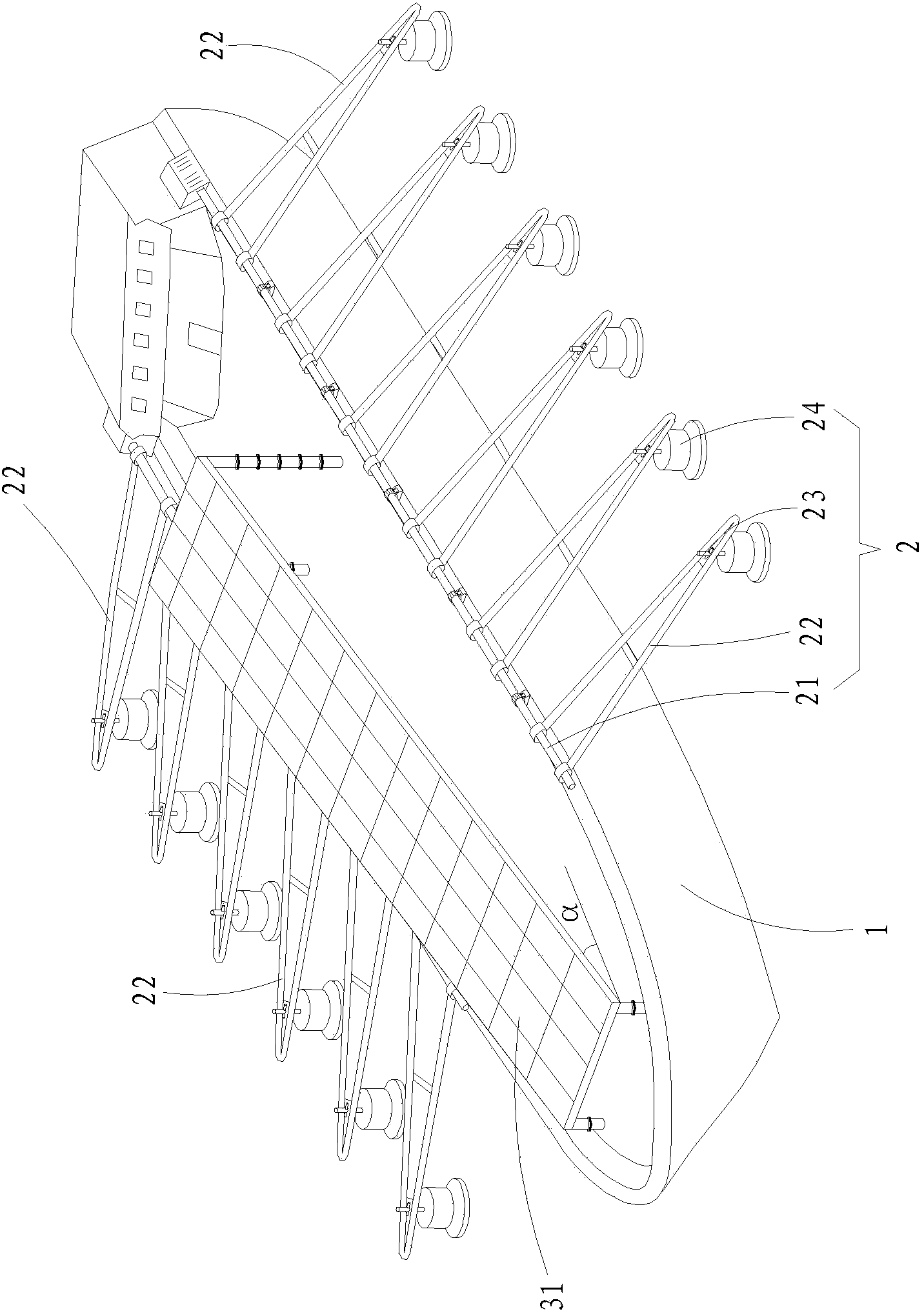
[0025] Example: see Figure 1 to Figure 4 , a mobile photovoltaic wave power ship, including a mobile hull 1, a wave energy conversion device 2, a photovoltaic cell assembly 3, a planetary power box 4 and a generator 5, wherein:

[0026] Mobile hull 1, which is the carrier of the entire power generation system;

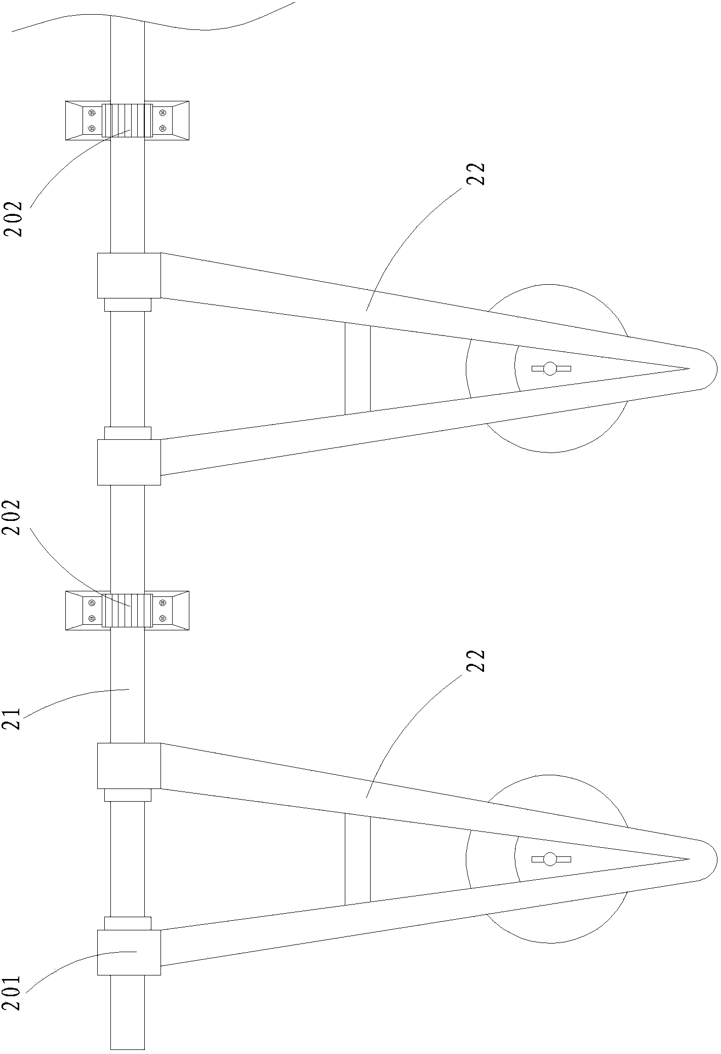
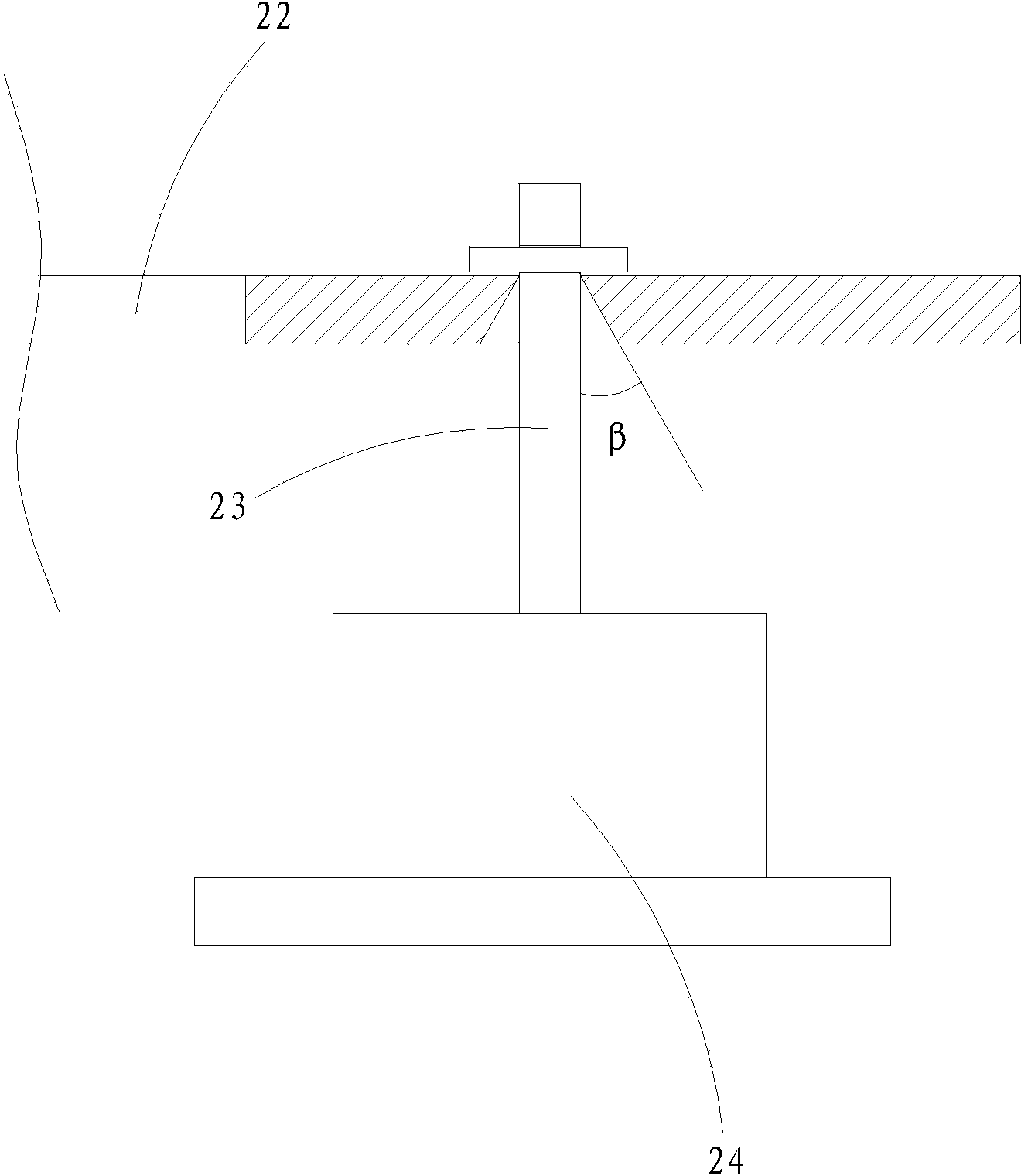
[0027] The wave energy conversion device 2 is symmetrically arranged on both sides of the hull. The wave energy conversion device 2 on each side includes a main shaft 21 on which a number of tripods 22 are installed. The outer ends of the tripods are connected to the floating body 24 through the hanging rod 23 , the inner end of the tripod 22 is connected to the main shaft 21 through the first overrunning clutch 201, the floating body 24 vibrates up and down under the action of the waves, and the wave energy is transmitted to the main shaft 21 through the tripod 22 and the overrunning clutch 201 and converted into mechanical energy, the hull 1 The main shaft 21 on bo...


PUM


Abstract

The invention discloses a movable photovoltaic wave power generation ship, which comprises a movable ship body, wave energy converting devices, a photovoltaic battery assembly, a planet power box and a generator, wherein the wave energy converting devices are symmetrically arranged on both sides of the ship body; the wave energy converting device on each side comprises a main shaft and a plurality of floating bodies; the floating bodies oscillate upwards and downwards under the action of wave; the wave energy is transmitted to the main shafts through triangular frames and overrunning clutches, and is converted into mechanical energy; the main shafts on both sides of the ship body are connected with the planet power box; the planet power tank is used for outputting mechanical energy to drive the generator to generate power; the electric energy generated by the photovoltaic battery assembly is connected to a storage battery for storage after being in grid-connection with the electric energy generated by the generator. By adopting the movable photovoltaic wave power generation ship, the generation forms of marine solar energy and wave energy are utilized comprehensively, so that the power compensation in a complex environment is realized, the stability of power output is ensured, and the grid connection is facilitated.

Description

technical field [0001] The invention discloses a mobile photovoltaic wave power generation ship, which belongs to the technical field of marine power generation equipment manufacturing according to the International Patent Classification (IPC). Background technique [0002] The Taiwan Strait of China is a strait connecting the South China Sea and the East China Sea between Fujian Province and Taiwan Province. Its average water depth is about 60 meters, and it belongs to the south subtropical and north tropical monsoon climate. -Northern waves dominate, and southwest-south waves dominate in the southwest monsoon season. The application of such abundant wind energy and wave energy to power generation is an effective way to solve energy shortages. [0003] At present, the common power generation technologies at sea mainly include wave power generation, tidal power generation, offshore wind power generation, ocean current power generation, and offshore solar power generation. Ho...

Claims


Application Information

Patent Timeline
Patent Type & Authority Applications(China)
IPC IPC(8): F03B13/16H02S10/40H02S20/32B63B35/00
CPCY02E10/30Y02E10/50
Inventor 郑章明
Owner 厦门中泰风电能源有限公司
Why Eureka
Try Eureka