Positioning system based on multi-directional polarized light navigation sensor and positioning method of positioning system

A direction sensor and positioning system technology, applied in navigation, astronomical navigation, ground navigation and other directions, can solve problems such as difficult precise positioning, easy to be interfered, and complicated calculation process, and achieve simple structure, strong anti-interference ability, and high precision Effect

Active Publication Date: 2014-05-28
DALIAN UNIV OF TECH
View PDF8 Cites 33 Cited by
  • Summary
  • Abstract
  • Description
  • Claims
  • Application Information

AI Technical Summary

Problems solved by technology

Satellite and radio navigation are susceptible to interference due to man-made signals
Inertial navigation errors accumulate over time, making precise positioning difficult
The device cost of celestial navigation is high, and the calculation process is complicated
The patent number disclosed in the prior art: (CN 103115623A), the positioning technology with polarized light navigation technology as the core, cannot realize real-time positioning. This technical solution needs to measure the maximum polarization direction of the polarized light angle sensor at different times in order to calculate the latitude and longitude

Method used


Image

  • Positioning system based on multi-directional polarized light navigation sensor and positioning method of positioning system
  • Positioning system based on multi-directional polarized light navigation sensor and positioning method of positioning system
  • Positioning system based on multi-directional polarized light navigation sensor and positioning method of positioning system

Examples


Embodiment

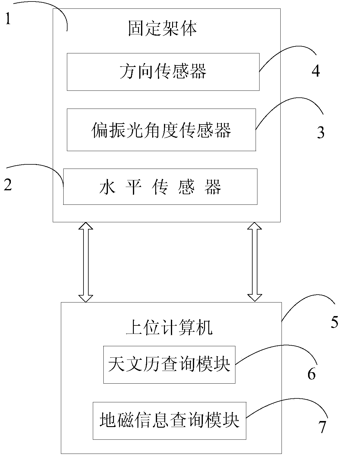
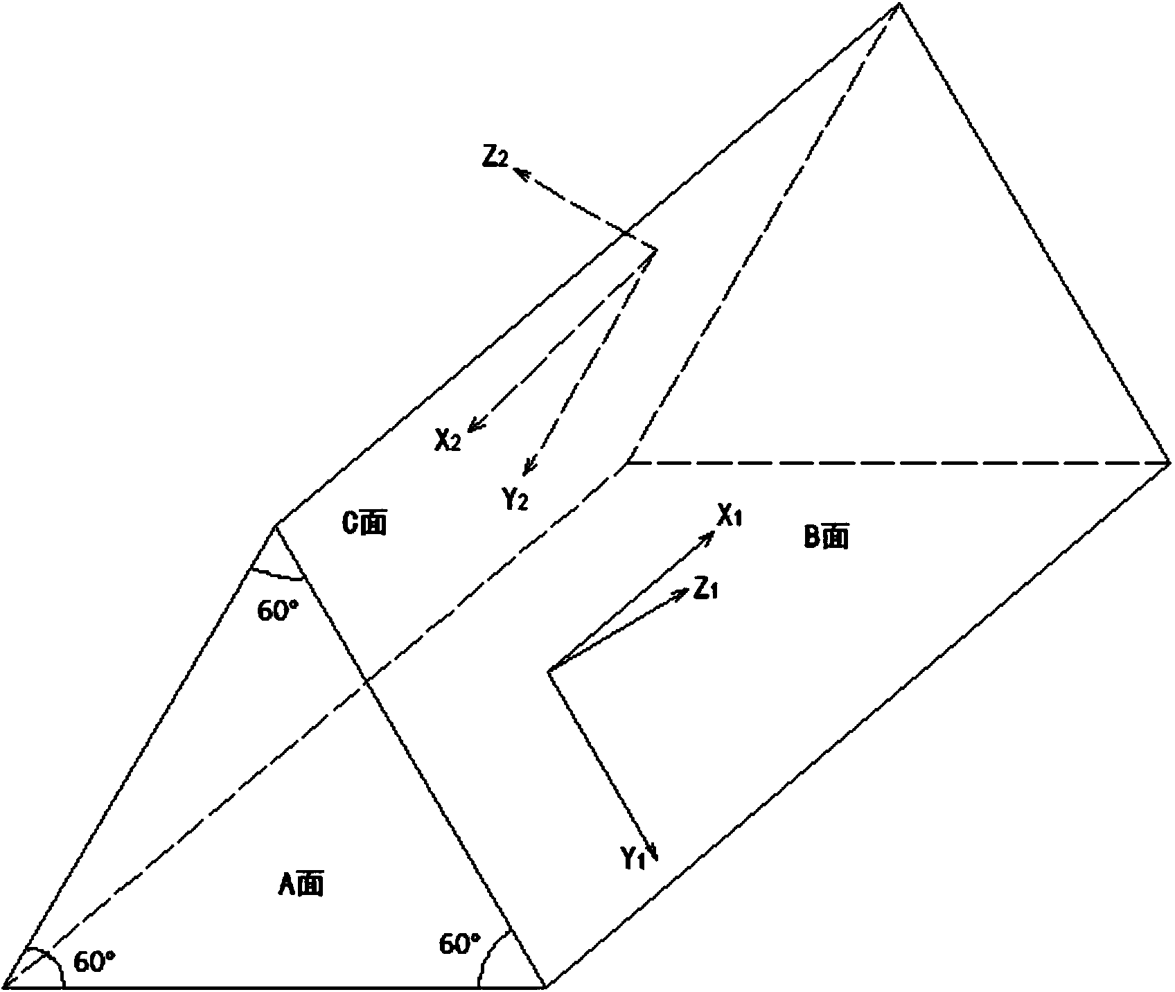
[0046] Such as image 3 Shown is a schematic diagram of an embodiment of the present invention: the fixed frame body 1 is set to be composed of three planes, namely A, B, and C, and the angle between the A plane and the B plane is set to 60°, and the A plane The angle between the surface C and the surface C is set to 60°, the angle between the surface B and the surface C is set to 60°, the three intersection lines between the A surface, the B surface and the C surface are parallel to each other, and the direction sensor 4 And the level sensor 2 is installed on the A face of the fixed frame body 1, and the polarized light angle sensor 3 is installed on the B face and the C face, and the direction sensor 4, the polarized light angle sensor 3 and the level sensor 2 are connected to the host computer through the data line 5 to carry out data communication, and transmit the collected data information to the host computer 5 . The astronomical calendar query module 6 and the geomagn...


PUM


Abstract

The invention discloses a positioning system based on a multi-directional polarized light navigation sensor. The positioning system comprises a fixed frame and an upper computer, wherein polarized light angle sensors for measuring the maximum polarization direction of incident light are installed on any two planes respectively, a level sensor and a direction sensor are installed on a datum plane of the fixed frame, and an astronomical calendar query module and a geomagnetic information query module are arranged in the upper computer. According to the system, a polarized light navigation technology and astronomical knowledge are combined, measured values of the level sensor, the polarized light angle sensor and the direction sensor on the fixed frame are obtained, geomagnetic declination data information is queried through the geomagnetic information query module in the upper computer, sun declination delta values at certain moments and true sun time differences on certain days are queried through the astronomical calendar query module, and the longitude and the latitude of a carrier are obtained through calculation by using an algorithm disclosed in the invention according to the data information.

Description

technical field [0001] The invention relates to a positioning system and a positioning method thereof, in particular to a positioning system based on a multi-directional polarized light navigation sensor and a positioning method thereof. Background technique [0002] The current positioning technology mainly includes satellite navigation, inertial navigation, astronomical navigation and radio navigation. Satellite and radio navigation are susceptible to interference due to man-made signals. Inertial navigation errors accumulate over time, making precise positioning difficult. The device cost of celestial navigation is high, and the calculation process is complicated. The patent number disclosed in the prior art: (CN 103115623A), the positioning technology with polarized light navigation technology as the core, cannot realize real-time positioning. This technical solution needs to measure the maximum polarization direction of the polarized light angle sensor at different ti...

Claims


Application Information

Patent Timeline
IPC IPC(8): G01C21/00G01C21/02
CPCG01C21/00G01C21/02G01C21/08
Inventor 褚金奎王寅龙张然王璐王志文关乐崔岩
Owner DALIAN UNIV OF TECH
Why Eureka
Try Eureka