Quick dynamic reactive-power compensating method of combined electrical load

A technology of electric load and compensation method, applied in the direction of reactive power compensation, reactive power adjustment/elimination/compensation, etc., to achieve the effect of reducing the withstand voltage level and requirements and the use environment

Inactive Publication Date: 2014-05-28
WUHAN UNIV OF TECH
View PDF4 Cites 21 Cited by
  • Summary
  • Abstract
  • Description
  • Claims
  • Application Information

AI Technical Summary

Problems solved by technology

However, the compensator is mainly used in static reactive power comp

Method used


Image

  • Quick dynamic reactive-power compensating method of combined electrical load

Examples


Embodiment Construction

[0037] The present invention will be further described below in conjunction with implementation and accompanying drawings, but the present invention is not limited.

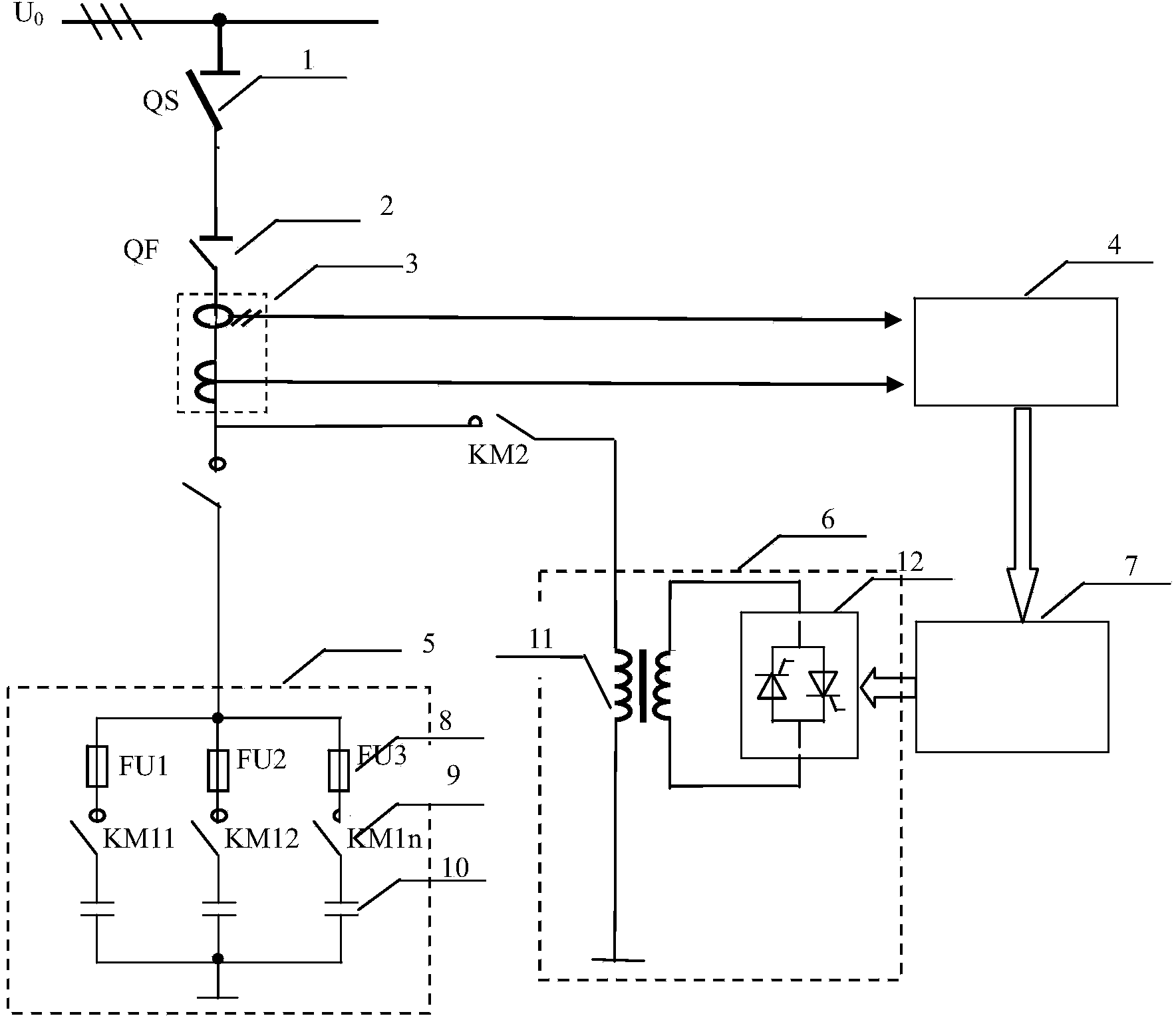
[0038] The dynamic reactive power fast compensation method of the composite power load provided by the present invention controls the power electronic power converter 12 through the intelligent controller 7, changes the current and impedance of the secondary winding of the varactor 11, thereby changing the The current and impedance of the primary winding of the anti-transformer. When the input voltage is constant, changing the admittance of the varactor 11 can change the fundamental wave current, thereby causing the change of the reactive power absorbed by the varactor 11 . The adjustable capacitor bank 5 is controlled by the intelligent controller 7 and compensated to the target power factor. The inductive reactance converter 6 cooperates with the adjustable capacitor bank 6 to smoothly adjust reactive power and...


PUM


Abstract

The invention provides a quick dynamic reactive-power compensating method of combined electrical load. The method is characterized in that a power electronic power converter (12) is controlled by an intelligent controller (7) to change the current and the impedance of a secondary winding of a variable reactor (11), so as to change the current and the impedance of a primary winding of the variable reactor (11); the fundamental current is changed by changing the admittance of the variable reactor when the input voltage is unchanged, so that the change of the variable reactor absorbing reactive power is caused; when an adjustable capacitor bank (5) is controlled by the intelligent controller and the target power factor is compensated, an inductive reactance convertor (6) can slide to adjust the reactive power in cooperation with the adjustable capacitor bank; therefore, the dynamic reactive-power compensation of the combined electrical load is realized. The method can realize real-time analysis and extraction of reactive power and reactive current under different load conditions, so as to realize intelligent control of the optimal quick reactive-power compensation; and the method can be used for quick reactive-power compensation of the combined high-voltage electrical load in the industries such as metallurgy, building materials, petrifaction and the like.

Description

technical field [0001] The invention relates to the field of dynamic reactive power compensation, in particular to a dynamic reactive power fast compensation method for composite electric loads. Background technique [0002] With the development of the power system, various new impact loads (such as industrial electric arc furnaces, electric locomotives, rolling mills, etc.) cause frequent voltage fluctuations on the low-voltage distribution network, and large-scale semiconductor rectifiers cause harmonics in the power grid, which affects the quality of the voltage. Deterioration affects the work of other equipment in the grid. At the same time, a large number of new sensitive equipment (such as semiconductor manufacturing plants, etc.) has emerged, which puts forward higher requirements for power quality. Therefore, there is an urgent need for control equipment to improve power quality. [0003] Current reactive power compensation technologies mainly include capacitor com...

Claims


Application Information

Patent Timeline
IPC IPC(8): H02J3/18
CPCY02E40/30
Inventor 陈静程琪戬袁佑新王一飞肖純杨威周斌
Owner WUHAN UNIV OF TECH
Why Eureka
Try Eureka