High-speed large-current power field-effect transistor driving circuit

A power field effect tube and drive circuit technology, applied in the direction of output power conversion devices, electrical components, etc., can solve problems that cannot meet high frequency and load capacity applications

Active Publication Date: 2014-05-28
WUXI YANAO ELECTRONICS TECH
View PDF6 Cites 12 Cited by
  • Summary
  • Abstract
  • Description
  • Claims
  • Application Information

AI Technical Summary

Problems solved by technology

[0004] The existing integrated drive circuits dedicated to drive power MOSFETs and IGBTs cannot meet high-frequency applications with strong load capacity. For exam

Method used


Image

  • High-speed large-current power field-effect transistor driving circuit
  • High-speed large-current power field-effect transistor driving circuit
  • High-speed large-current power field-effect transistor driving circuit

Examples


Example Embodiment

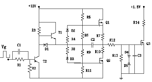
[0018] like figure 1 Among them, the driving pre-circuit is connected with the driving signal Vg, and the driving pre-circuit includes a capacitor C1, resistors R1, R2, R3, a diode D1 and triodes T1, T2, and the capacitor C1 is connected between the driving signal Vg and the base of the triode T2 ; The resistor R1 is connected in parallel with the capacitor C1, the resistor R2 is connected between the base and the emitter of the transistor T2, and the resistor R3 is connected between the emitter and the base of the transistor T1; the anode of the anti-reverse diode D1 is connected to the collector of the transistor T1, The negative electrode of D1 is connected to the collector of the triode T2; the triode T1 is an NPN type triode, the emitter of T1 is connected to the +12V voltage, and the triode T2 is a PNP type triode; the driving rear circuit is connected to the driving object Q3, and the driving rear circuit includes a resistor R12~R13, diodes D4 and D5, capacitor C3 and F...


PUM


Abstract

The invention discloses a high-speed large-current power field-effect transistor driving circuit, which comprises a driving pre-circuit, a totem-pole circuit, and a driving post-circuit, wherein the driving pre-circuit comprises a capacitor C1, resistors R1, R2 and R3, a diode D1 and triodes T1 and T2; the totem-pole circuit consists of diodes D2 and D3, resistors R4 to R11, a capacitor C2 and field-effect transistors Q1 and Q2; the driving post-circuit consists of resistors R12 and R13, diodes D4 and D5, a capacitor C3 and a field-effect transistor Q3; the driving pre-circuit is connected with a driving signal Vg, the driving post-circuit is connected with a driving object Q3, and the totem-pole circuit is connected with the driving pre-circuit and the driving post-circuit. The driving circuit is simple in structure, low in cost, large in output current and high in load-carrying capacity, and can meet the requirement on the high-speed low-voltage large-current driving on the field-effect transistors under specific situations.

Description

technical field [0001] The invention belongs to the technical field of power electronic drive application, and in particular relates to a high-speed and high-current power field effect transistor drive circuit. The drive circuit has large output current and strong load capacity, and is suitable for high-speed, low-voltage, high-current driving of field effect transistors under specific circumstances. the occasion. Background technique [0002] With the development of power semiconductor devices, a variety of fully controlled devices have appeared, the most commonly used are high-power transistors (GTR) suitable for high-power occasions, and power transistors suitable for medium and small power occasions but with better rapidity Field Effect Transistors (MOSFETs) and Power Insulated Gate Bipolar Transistors (IGBTs) resulting from the combination of GTRs and power MOSFETs. [0003] Among these switching devices, power MOSFET has become the most commonly used device in switch...

Claims


Application Information

Patent Timeline
IPC IPC(8): H02M1/088
Inventor 唐余武邹坤
Owner WUXI YANAO ELECTRONICS TECH
Why Eureka
Try Eureka