Hot rolling equipment

A technology for equipment and rolling mills, applied in the field of hot rolling equipment, can solve problems such as poor shape, lowering of intermediate billet temperature, and quality damage, and achieve the effect of ensuring stability, uniform temperature difference, and preventing damage to quality or productivity.

Active Publication Date: 2016-01-20
PRIMETALS TECHNOLOGIES JAPAN LTD
View PDF6 Cites 0 Cited by
  • Summary
  • Abstract
  • Description
  • Claims
  • Application Information

AI Technical Summary

Problems solved by technology

[0009] However, in the hot rolling facility disclosed in Patent Document 1, when a thick slab is reversibly rolled by a roughing mill in the second rolling line, the temperature of the front and rear ends of the intermediate billet decreases, and there are also problems as follows Points: Defective shapes such as fishtails or flat tails are generated at the front and rear ends of the intermediate billet, lack of stability in final rolling or coiling in the first rolling line, and impair quality
[0010] In addition, in the rolling of the thick slab in the second rolling line, since the material heated by the batch heating furnace is rolled, the time from tapping to rough rolling varies depending on the position in the longitudinal direction of the material, and There is also a problem that the temperature in the longitudinal direction of the intermediate billet transferred to the first rolling line is different, so that the stability of rolling in the first rolling line and the quality of the final product are impaired.

Method used


Image

  • Hot rolling equipment
  • Hot rolling equipment

Examples


Embodiment 1

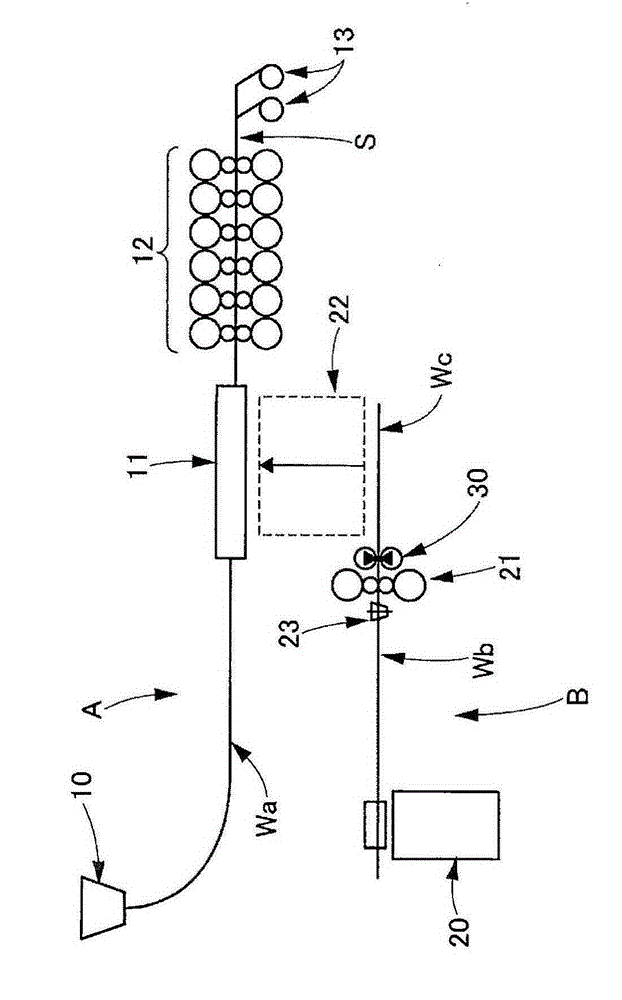
[0022] figure 1 It is a side view showing the schematic structure of the hot rolling facility according to Example 1 of the present invention.

[0023] like figure 1 As shown, molten steel is injected into a tundish from a ladle not shown, and is injected into the continuous casting machine 10 from the tundish. In this continuous casting machine 10, molten steel solidifies to become a high-temperature thin slab Wa (for example, about 70 to 100 mm). The thin slab Wa advances to the soaking furnace (continuous casting machine output side furnace) 11, and the temperature drop of the thin slab Wa is suppressed in the soaking furnace 11, and the temperature distribution in the thin slab Wa is uniformized. In addition, a cutting machine (not shown) that cuts the slab when it reaches a desired length is provided on the output side of the continuous casting machine 10 .

[0024] The thin slab Wa coming out of the soaking furnace 11 is finished rolled by a plurality of (in the illus...

Embodiment 2

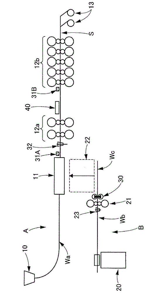
[0032] figure 2 It is a side view showing a schematic structure of a hot rolling facility according to Example 2 of the present invention.

[0033] like figure 2 As shown, this embodiment is an example in which the plurality of rolling mills (columns) 12 of the first rolling line A in Embodiment 1 are divided into one or more stands (in the illustrated example, two stands) The upstream side rolling mill 12a consisting of one stand) and the downstream side rolling mill 12b consisting of more than one stand (five stands in the illustrated example) are located on the intermediate table between the above-mentioned upstream side rolling mill 12a and the downstream side rolling mill 12b. A material temperature adjusting device 40 is provided which adjusts the temperature of the slab (thin slab Wa or intermediate slab Wc) rolled by the upstream side rolling mill 12a by cooling water or a heating device or the like.

[0034]In other configurations, on the input side of the upstrea...


PUM


Abstract

In order to provide a hot rolling facility with which an improvement in the manufacturability and the quality of a thin plate material can be achieved with little facility investment, this hot rolling facility is equipped with a first rolling line (A), which directly performs finishing rolling with multiple rolling mills (12) on a thin slab (Wa) cast with a continuous-casting machine (10), and a second rolling line (B), which is arranged parallel to the first rolling line (A) and, with a roughing mill (21), reversibly rolls a thick slab (Wb) heated in a batch-type heating furnace (20) , with an intermediate material (Wc) that has been rolled with the second rolling line (B) being transported to the first rolling line (A) and undergoing finishing rolling at the first rolling line (A) to produce a final product (S). A crop shear device (30) that cuts and evens up the front and rear ends of the intermediate material (Wc) rolled with the roughing mill (21) is installed in the second rolling line (B).

Description

technical field [0001] The present invention relates to a hot rolling facility capable of improving the productivity and quality of thin plates with a small investment in facilities. Background technique [0002] Conventionally, for example, Patent Document 1 discloses a hot-rolling facility including a first rolling line and a second rolling line, and the first rolling line directs a thin slab cast by a continuous casting machine to a thin slab cast by a plurality of rolling mills. Finish rolling, the second rolling production line is arranged in parallel with the first rolling production line, and the thick slab heated by the batch heating furnace is used to roll the rough rolling mill, and the hot rolling equipment will be controlled by the first The intermediate billet rolled by the second rolling line is transferred to the first rolling line, and is finished rolled to a final product by the first rolling line. [0003] As a result, by transferring slabs of various slab...

Claims


Application Information

Patent Timeline
Patent Type & Authority Patents(China)
IPC IPC(8): B21B1/26B21B1/46B21B15/00B21B45/00B22D11/12
CPCB21B1/26B21B1/463B21B39/004B21B45/004B21B2015/0014
Inventor 木之濑亮平
Owner PRIMETALS TECHNOLOGIES JAPAN LTD
Why Eureka
Try Eureka