
Piston for a free piston engine generator

A piston engine, driven technology, applied in the field of pistons

Active Publication Date: 2014-05-28
LIBERTINE FPE
View PDF6 Cites 0 Cited by
  • Summary
  • Abstract
  • Description
  • Claims
  • Application Information

AI Technical Summary

Problems solved by technology

This change in diameter requires complex and expensive mechanical methods to seal each combustion chamber and ensure they are coaxially aligned with each other and with the shaft of the motor in the middle

Method used


Image

  • Piston for a free piston engine generator
  • Piston for a free piston engine generator
  • Piston for a free piston engine generator

Examples


Embodiment Construction

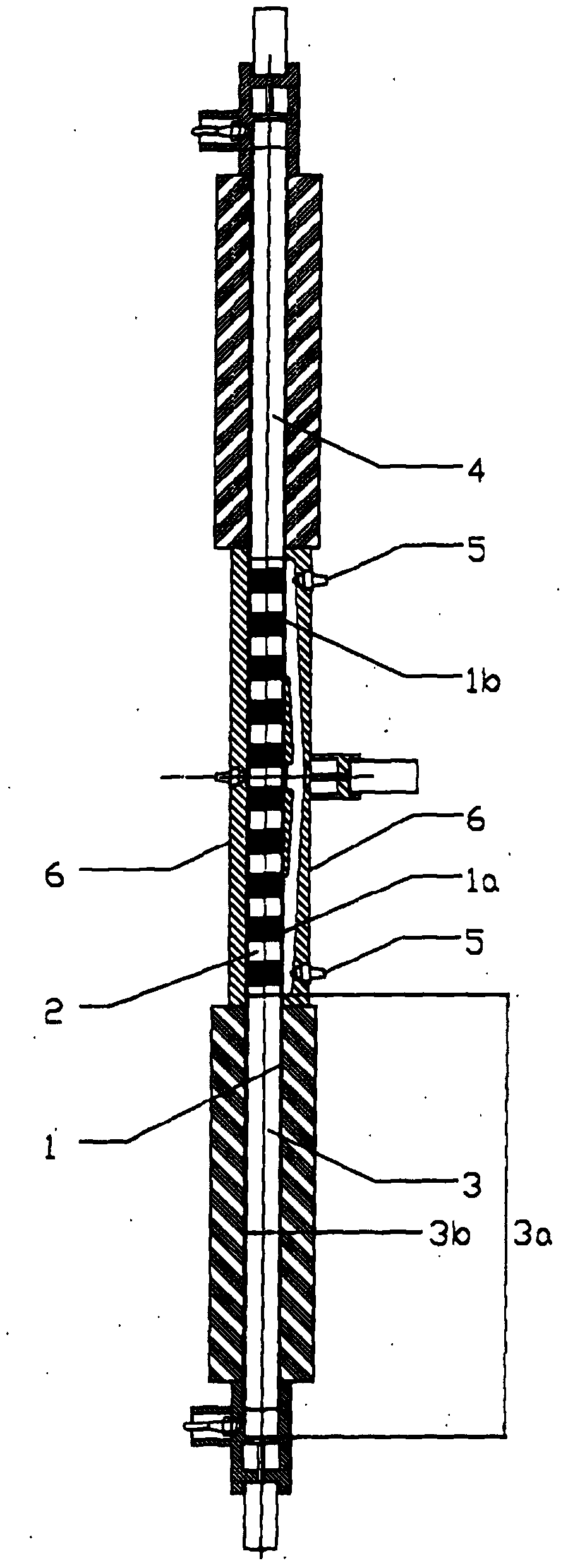
[0079] figure 1 An example of the present invention provided in a free-piston engine-driven power generation system is shown. It can be seen that the piston 2 is free to move along the length of the cylinder 1, and that the piston is constrained to be coaxially aligned with the cylinder 1, thereby effectively dividing the cylinder 1 into a first combustion chamber 3 and a second combustion chamber 4, each chamber according to the position of the piston 2 in The position in cylinder 1 has variable volume. No part of piston 2 protrudes from cylinder 1. Using the first chamber 3 as an example, each of the chambers 3, 4 has a variable height 3a and a fixed diameter 3b.

[0080] Preferably, the cylinder 1 is rotationally symmetric about its axis and about a central plane perpendicular to its axis. Arrangements with circular cross-section pistons are preferred, although other geometries may be used to practice the invention, such as pistons with square or rectangular cross-sectio...


PUM


Abstract

A piston for a free piston engine generator, comprising one or more elements arranged coaxially along a piston shaft wherein the length of the piston is at least five times its maximum diameter, wherein at least one of the elements is formed from a magnetically permeable composite material having isotropic electrical resistivity at least twice that of electrical steel, this arrangement providing improved free piston position control, more consistent combustion and improved electrical conversion efficiency.

Description

technical field [0001] The present invention relates to a piston, in particular to a piston for a free-piston engine-driven generator. Background technique [0002] In a conventional internal combustion engine, a piston is mechanically confined within its cylinder by being connected to a crankshaft which is rotationally driven by the reciprocating linear movement of the piston within the cylinder. However, in a free piston engine the pistons are not connected to the crankshaft, although pistons may be provided in generators of this type with an external mechanical coupling such as taught in US-A-7383796. [0003] Further, it is known to generate electricity by changing the magnetic flux produced by the movement of a reciprocating piston through one or more electric coils in a free piston engine, eg US-A-7318506. In this arrangement, the piston carries a first coil and as it reciprocates in the cylinder it induces a current in a second coil surrounding the cylinder. However...

Claims


Application Information

Patent Timeline
Patent Type & Authority Applications(China)
IPC IPC(8): F02B71/04F02B63/04H02K7/18
CPCF02B63/041H02K7/1884F02F3/0084H02K2213/03F02B71/04Y10T29/49249Y10T29/49231F02B71/00F02F3/0015H01K7/00H02K7/18
Inventor 塞缪尔·爱德华·科克里尔
Owner LIBERTINE FPE
Learn More