A kind of group tower crane with jib
What is Al technical title?
Al technical title is built by PatSnap Al team. It summarizes the technical point description of the patent document.
A tower crane and crane technology, applied in cranes and other directions, can solve the problems of inability to meet the long cross arm of UHV lines, the need for heavy tower assembly, the large cross-sectional size and weight of the tower body, and the lack of installation of a balance arm. The effect of convenient collaborative operation, less space occupation, and flexible speed control
Active Publication Date: 2015-11-25
STATE GRID CORP OF CHINA +1
View PDF11 Cites 0 Cited by
Summary
Abstract
Description
Claims
Application Information
AI Technical Summary
This helps you quickly interpret patents by identifying the three key elements:
Problems solved by technology
Method used
Benefits of technology
Problems solved by technology
[0004] In the prior art, there is also a tower crane developed by China Electric Power Research Institute, which adopts the design scheme of single boom and no balance arm, and is applied in the construction of UHV transmission lines. Short arm length (simply lengthening the boom will lead to a significant increase in the overall weight), lack of installation of balance arms and other deficiencies, resulting in a large cross-sectional size and weight of the tower body, which cannot meet the needs of UHV lines with long cross-arms and heavy-weight iron towers. immediate need
Method used
Image
Click on the blue label to locate the original text in one second.
Reading with bidirectional positioning of images and text.
Examples
Embodiment Construction
[0031] Below in conjunction with accompanying drawing, the special-purpose tower crane for erecting iron tower construction with auxiliary arm of the present invention is described in further detail.
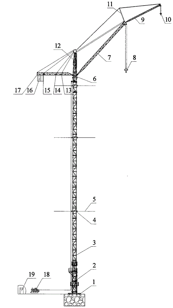
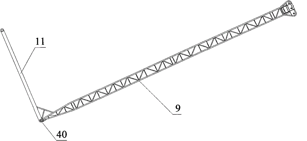
[0032] Such as figure 1 As shown, a special-purpose tower crane with a jib for erecting transmission line iron towers according to an embodiment of the present invention mainly includes: a steel structure base 1, a jacking frame 2, a tower body 3, an attachment frame 4, Attached wire rope 5, slewing support device 6, main arm 7, main hook 8, auxiliary arm 9, auxiliary hook 10, strut 11, tower head 12, auxiliary arm luffing mechanism 13, main arm luffing mechanism 14, auxiliary lifting Mechanism 15, counterweight 16, balance arm 17, main lifting mechanism 18 and control room 19.
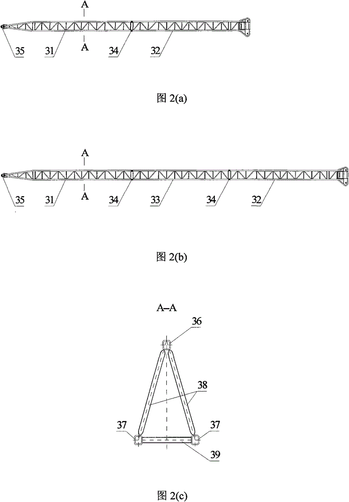
[0033] The main boom 7 is a space truss structure, which is assembled by connecting 2 to 3 boom sections through pin shafts. figure 2 Shown is a schematic diagram of the main arm 7, wherein figure ...
PUM
Abstract
The invention provides a group tower type crane with an auxiliary boom, which comprises a steel structure base, a jacking sleeve frame, a tower body, an attaching frame, an attaching steel wire rope, a rotary support device, a main boom, an auxiliary boom, a main hook, an auxiliary hook, a support rod, a tower head, a main boom luffing mechanism, an auxiliary boom luffing mechanism, a hoisting mechanism, a balance arm, a balance weight and a control chamber, wherein one end of the main boom is hinged on the rotary support device, and makes a pitching movement in a vertical plane around a hinge point under the drawing of the main boom luffing mechanism, the other end of the main boom is connected with the main hook and the auxiliary boom, one end of the auxiliary boom is fixedly connected with the lower end of the support rod, the other end of the auxiliary boom is connected with the auxiliary hook, and the auxiliary boom and the support rod are integrally hinged on the end part of the main boom, and make a pitching movement in the vertical plane around the hinge point under the drawing of the auxiliary boom luffing mechanism. Through additionally providing the auxiliary boom, the working amplitude of a tower crane is greatly improved; and the group tower type crane is especially suitable for assembling construction of an extra-high voltage iron tower which is longer in length of a cross arm and larger in weight.
Description
technical field [0001] The invention belongs to the field of construction equipment for overhead transmission lines, and in particular relates to a special tower crane with a jib for erecting transmission line iron towers. Background technique [0002] The erection construction of poles and towers is a construction link with heavy workload, high construction difficulty and many risk factors in the construction of transmission lines. At present, large mobile cranes or helicopters are mainly used for tower construction in foreign countries. For example, the United States, Canada and other countries have generally used large mobile cranes or helicopters for tower construction, while the main equipment for domestic tower construction is various forms of poles. The poles for power transmission and transformation construction (including single poles, rocker poles, etc.) are light and small lifting equipment. They are simple lifting equipment commonly used in the construction of ov...
Claims
Application Information
Patent Timeline
Application Date:The date an application was filed.
Publication Date:The date a patent or application was officially published.
First Publication Date:The earliest publication date of a patent with the same application number.
Issue Date:Publication date of the patent grant document.
PCT Entry Date:The Entry date of PCT National Phase.
Estimated Expiry Date:The statutory expiry date of a patent right according to the Patent Law, and it is the longest term of protection that the patent right can achieve without the termination of the patent right due to other reasons(Term extension factor has been taken into account ).
Invalid Date:Actual expiry date is based on effective date or publication date of legal transaction data of invalid patent.