
High efficiency cavitation air flotation precipitation machine

A vortex and high-efficiency technology, which is applied in the field of high-efficiency concave vortex air flotation sedimentation machines, can solve the problems of inability to carry out large-scale and wide application, the stability of effluent water cannot be guaranteed, and the water quality requirements of influent water, etc., so as to save equipment, The effect of ingenious design and improved removal efficiency

Active Publication Date: 2014-06-04
CHANGZHOU JIANGNAN ENVIRONMENTAL ENG
View PDF7 Cites 15 Cited by
  • Summary
  • Abstract
  • Description
  • Claims
  • Application Information

AI Technical Summary

Problems solved by technology

[0004] Due to the selective removal of suspended solids in water by air flotation (the effect of suspended solids close to 1 is the best), all the above air flotation technologies have certain defects, and there are many industries, scopes of use, and requirements for water quality. Due to the limitation of application, the quality of influent water is required, the stability of effluent water cannot be guaranteed, and it cannot be used on a large scale and widely. In most cases, it appears in the process as pretreatment or advanced treatment, and cannot independently undertake water treatment as a core process. deal with

Method used


Image

  • High efficiency cavitation air flotation precipitation machine
  • High efficiency cavitation air flotation precipitation machine
  • High efficiency cavitation air flotation precipitation machine

Examples


Embodiment Construction

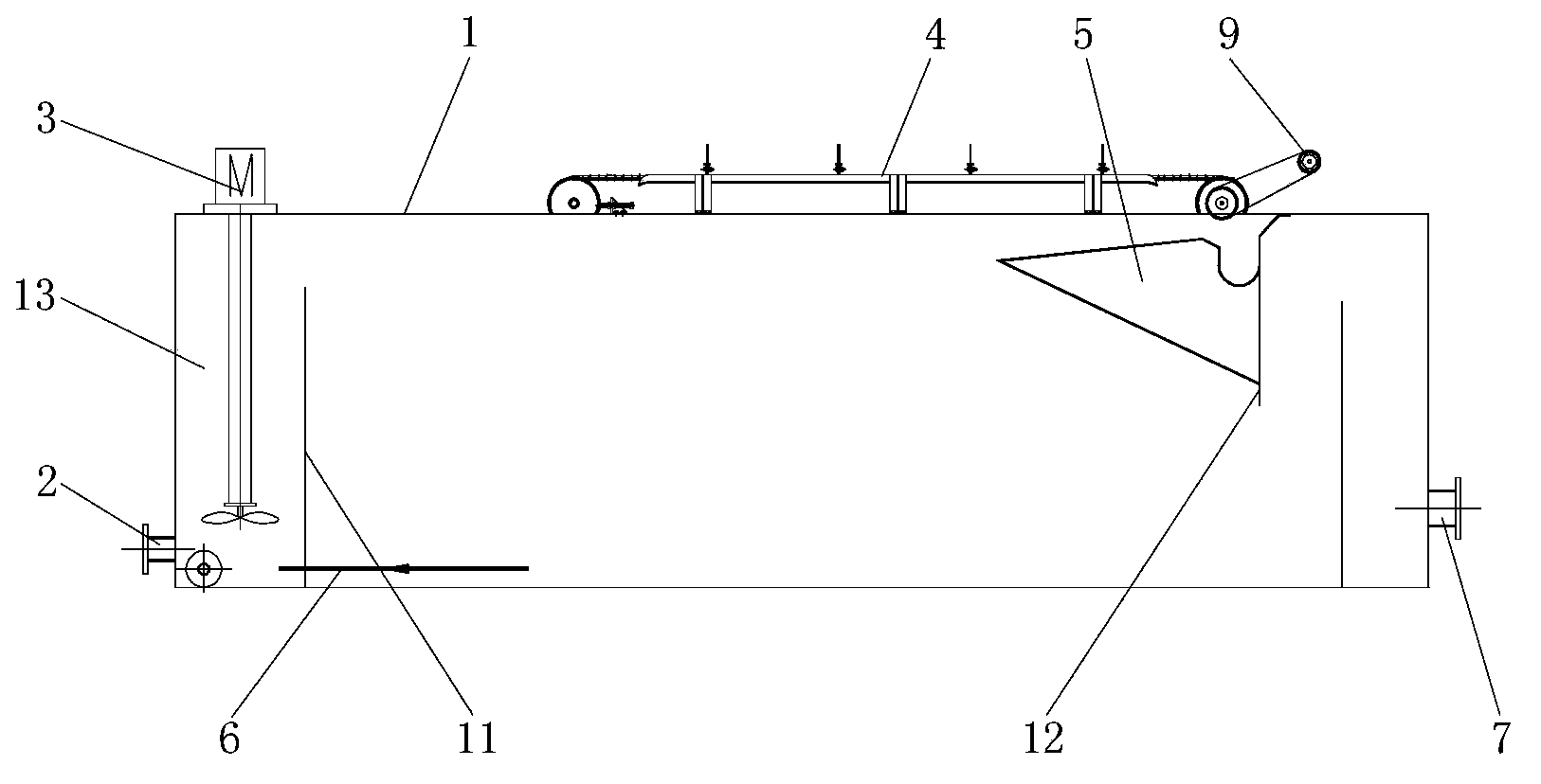
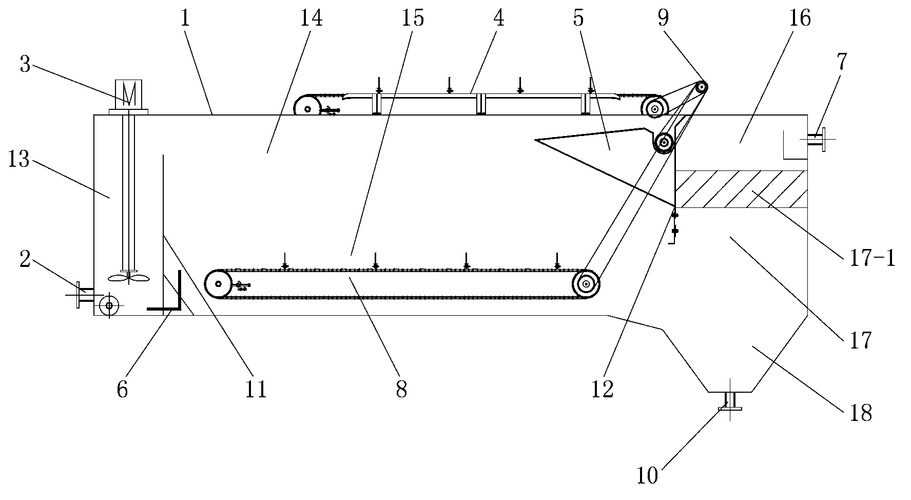
[0014] see figure 2 with image 3 , The present invention includes a pool body 1, a water inlet 2, a vortex air flotation machine 3, a froth scraper 4, a spiral froth conveyor 5, a return pipe 6 and a water outlet 7; the inner left side of the pool body 1 is provided with The left partition 11, the left side area of ​​the left partition 11 is the contact zone 13, the vortex air floatation machine 3 is arranged in the contact zone 13, and the outlet of the contact zone 13 is opened at the upper end; the inner right side of the pool body 1 is arranged There is a right partition 12, between the right partition 12 and the left partition 11 is the treatment area, the foam scraper 4 is arranged at the upper end of the treatment area and fixed on the tank body 1; the spiral foam conveyor 5 is installed on the scraper The bottom right side of the foaming machine 4; the bottom of the contact zone 13 is connected to the treatment zone through the return pipe 6; the treatment zone is div...


PUM


Abstract

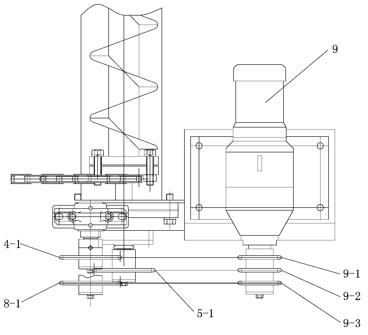
The invention relates to a high efficiency cavitation air flotation precipitation machine, which comprises a pool body, a water inlet, a cavitation air flotation machine, a foam scraper, a spiral floating foam conveyor, a return pipe and a water outlet. The inside of the pool body is divided into a contact area, a processing area, and a second processing area in terms of function. The cavitation air flotation machine is disposed in the contact area. The foam scraper is disposed at the upper end of the processing area and is fixed on the pool body. The spiral floating foam conveyor is mounted the right lower side of the foam scraper. The bottom of the contact area is communicated with the processing area through the return pipe. The bottom of the processing area is provided with a mud scraper. The second processing area falls into a clear water area, a sloping plate precipitation area, and a mud collecting hopper from top to bottom. The water outlet is arranged at the right upper end of the pool body and is in the clear water area. The foam scraper, the spiral floating foam conveyor and the mud scraper are driven by one speed reducer. Through ingenious design, the high efficiency cavitation air flotation precipitation machine provided by the invention effectively combines air flotation and precipitation, the effluent quality is more stable and reliable, and also the equipment and energy consumption are saved.

Description

Technical field [0001] The invention relates to a sewage treatment equipment, in particular to a high-efficiency concave vortex air flotation sedimentation machine. Background technique [0002] Air flotation and sedimentation technologies are two commonly used solid-liquid separation technologies in water treatment systems. Air flotation is the use of microbubbles generated by air entering the water to attach to pre-treated pollutants to form a gas-soil mixture, between the gas-soil mixture and the liquid Due to the imbalance of density, buoyancy is generated, and pollutants are brought to the water surface to be removed to achieve a water treatment technology to purify sewage; and sedimentation is the most commonly used method of solid-liquid separation by using the characteristics of particles to be heavier than water. Physical and chemical processing technology. In the current treatment process, these two technologies basically appear separately as monomer treatment processe...

Claims


Application Information

Patent Timeline
IPC IPC(8): C02F1/24C02F1/52
Inventor 杨发祥胡海华郭曼茹
Owner CHANGZHOU JIANGNAN ENVIRONMENTAL ENG
Learn More