Wheel-type coiled tubing injection device

A technology of injection device and oil pipe, applied in drill pipe, casing, drilling equipment, etc., can solve problems such as affecting the operation time and achieve the effect of good facility integrity, reduced manufacturing cost and simple structure

Inactive Publication Date: 2014-06-04
北京力源恒通科技有限公司
View PDF5 Cites 6 Cited by
  • Summary
  • Abstract
  • Description
  • Claims
  • Application Information

AI Technical Summary

Problems solved by technology

[0007] The purpose of the present invention is to provide a wheel-type coiled tubing injection device to simplify the structure of the coiled tubing injection device and reduce the manufacturing cost of the injection device; to use the guiding function of the injection wheel to solve the problems caused by the existing coiled tubing injection equipment. The mechanism and the injection mechanism are separated, and the injection mechanism and the guide mechanism need to be installed on site during the operation, which affects the working time.

Method used


Image

  • Wheel-type coiled tubing injection device
  • Wheel-type coiled tubing injection device
  • Wheel-type coiled tubing injection device

Examples


Embodiment Construction

[0022] In order to have a clearer understanding of the technical features, purposes and effects of the present invention, the specific implementation manners of the present invention will now be described with reference to the accompanying drawings.

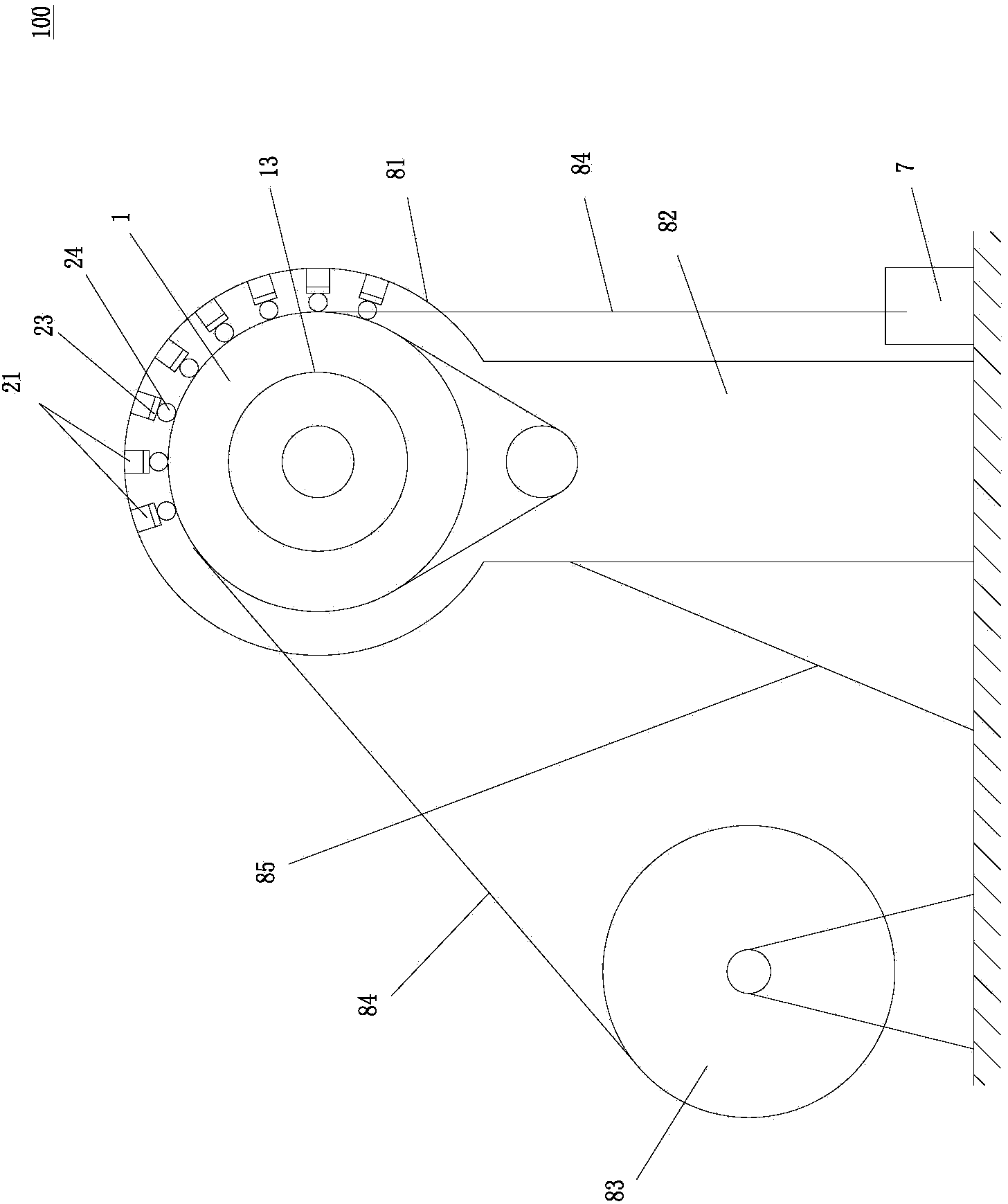
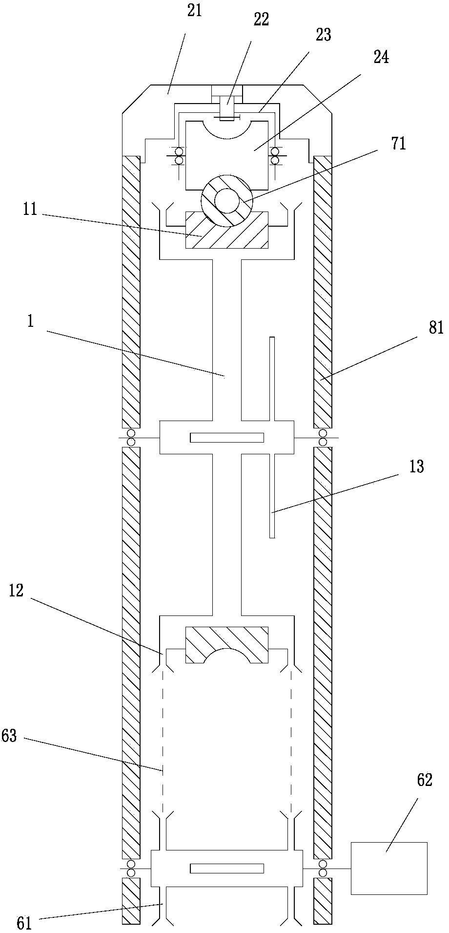
[0023] Such as figure 1 , figure 2 As shown, the present invention proposes a wheeled coiled tubing injection device 100. The injection device 100 includes an injection wheel 1 with a rotating shaft arranged horizontally. The injection wheel 1 is rotatably arranged on an injection wheel support frame 81 and is driven Driven by a transmission mechanism, the injection wheel support frame 81 is fixedly arranged on a frame 82, and the outer edge of the injection wheel support frame 81 is larger than the diameter of the injection wheel 1; around the upper circumferential surface of the injection wheel 1 (about One-third of the injection wheel) is provided with a plurality of fixed supports 21 that are arranged at intervals, and eac...


PUM


Abstract

The invention relates to a wheel-type coiled tubing injection device comprising an injection wheel provided with a horizontal rotary shaft. The injection wheel is rotatably disposed on an injection wheel support and driven by a transmission mechanism. The peripheral surface of the upper portion of the injection wheel is provided with a plurality of fixed bearings at intervals; the fixed bearings are fixed on the injection wheel support; the bottom of each fixed bearing is away from the peripheral surface of the injection wheel by a certain distance; a clamp wheel support is connected to the bottom of each fixed bearing through a clamping hydraulic cylinder; a clamp wheel is pivoted to each clamp wheel support; rotary shafts of the clamp wheels are parallel to the rotary shaft of the injection wheel. A coiled tube wound on a drum is wound on the injection wheel and pressed onto the surface of the injection wheel by the clamp wheels. The injection wheel is simple in structure, the whole structure of the injection device is simplified, and manufacture cost of the injection device is reduced. The injection wheel has a guide function; guide and injection functions are combined; field installation of an injection mechanism and a guide mechanism is avoided; construction efficiency is improved.

Description

technical field [0001] The invention relates to a coiled tubing injection device used for operations such as drilling, workover, oil testing, oil and gas production, and in particular to a wheeled coiled tubing injection device. Background technique [0002] Coiled tubing equipment is widely used in drilling, workover, oil testing, oil and gas production, stimulation and well completion. Such as image 3 As shown, the commonly used coiled tubing injection equipment 9 is mainly composed of a drum 91 for storing coiled tubing 94, a coiled tubing injection mechanism 92, a guide mechanism 93, a power system and a control system 95, and a truck-mounted crane for installing the injection mechanism and the guide mechanism. Machine (not shown in the figure) and other equipment, the above-mentioned special equipment is installed on the special chassis 96 or trailer to form a complete set of coiled tubing equipment that can be easily transported. The main function of the equipment is...

Claims


Application Information

Patent Timeline
Patent Type & Authority Applications(China)
IPC IPC(8): E21B19/22
Inventor 王树胜王景桐
Owner 北京力源恒通科技有限公司
Why Eureka
Try Eureka