Acoustic liner for air-inlet nacelle of aircraft engine and aircraft engine

An aero-engine and acoustic lining technology, applied in jet propulsion devices, gas turbine devices, machines/engines, etc., can solve problems such as complex structure, long development cycle, and limited fan rotor structural integrity requirements

Active Publication Date: 2014-06-04
AECC COMML AIRCRAFT ENGINE CO LTD
View PDF5 Cites 15 Cited by
  • Summary
  • Abstract
  • Description
  • Claims
  • Application Information

AI Technical Summary

Problems solved by technology

The first type of method is limited by the structural integrity requirements of the fan rotor, and its ability to reduce shock wave noise is limited. Therefore, advanced acoustic lining design is generally used in the existing fan shock wave noise reduction technology, and the design focus is on the material and quality of the acoustic lining. Its internal noise reduction structure, such as multi-degree-of-fr

Method used


Image

  • Acoustic liner for air-inlet nacelle of aircraft engine and aircraft engine
  • Acoustic liner for air-inlet nacelle of aircraft engine and aircraft engine
  • Acoustic liner for air-inlet nacelle of aircraft engine and aircraft engine

Examples


Example Embodiment

[0024] The present invention will be described more fully below with reference to the accompanying drawings, in which exemplary embodiments of the present invention are illustrated. The technical solutions in the embodiments of the present invention will be clearly and completely described below in conjunction with the accompanying drawings in the embodiments of the present invention. Obviously, the described embodiments are only a part of the embodiments of the present invention, rather than all the embodiments. Based on the embodiments of the present invention, all other embodiments obtained by those of ordinary skill in the art without creative work shall fall within the protection scope of the present invention. The technical solutions of the present invention will be described in various aspects below in conjunction with the figures and embodiments.

[0025] According to the shock wave attenuation theory of Morfey and Fisher, the shock wave intensity attenuation is related t...


PUM


Abstract

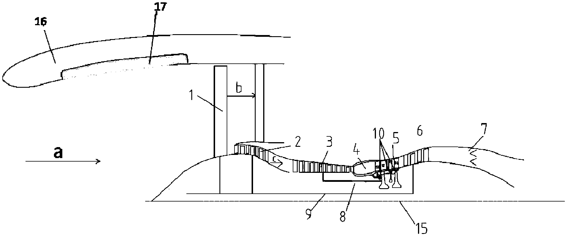
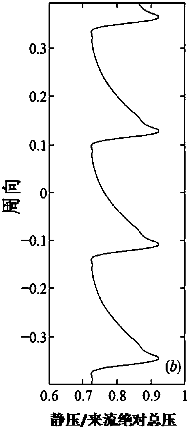
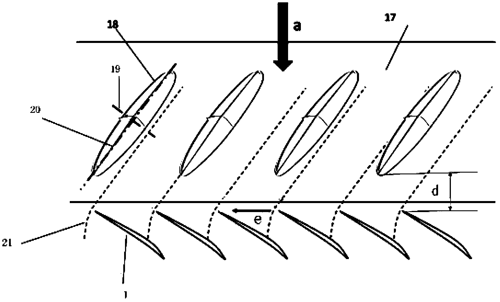
The invention discloses an acoustic liner for an air-inlet nacelle of an aircraft engine and the aircraft engine. The acoustic liner is arranged on the inner wall of the air-inlet nacelle and is characterized in that a plurality of convex hulls are arranged on the inner wall of the acoustic liner. According to the acoustic liner and the aircraft engine, the convex hulls are arranged in the acoustic liner, when airflow entering the nacelle of the engine flows through the convex hulls, the airflow is accelerated to increase the axial Mach number of a region so as to prolong the residence time of a shock wave in the region, so that the attenuation of the shock wave is accelerated, a purpose of reducing the noise of the shock wave is achieved, the performance of a fan can be improved as well, and the integral performance of the engine is improved.

Description

technical field [0001] The invention relates to the technical field of aeroengine fan aerodynamic noise, in particular to an acoustic lining device for an air intake nacelle of an aeroengine and an aeroengine. Background technique [0002] In a turbofan engine, especially a turbofan engine in a direct drive configuration, the tip region of the fan is supersonic with respect to the incoming flow and forms an outrigger and indenter shock at the leading edge. As the fan blades rotate, the pressure wave formed by the outstretched shock wave continues to propagate upstream, forming shock wave noise. In order to meet the requirements of civil aviation for low fuel consumption, the continuous increase of the bypass ratio of civil aeroengines has resulted in the increase of the outer diameter of the fan, which makes the fan shock wave noise the main noise source of the high bypass ratio turbofan engine. [0003] figure 1 It is a structural schematic diagram of a turbofan engine in...

Claims


Application Information

Patent Timeline
IPC IPC(8): F02C7/045
Inventor 邓向阳杨中郭福水闫嘉超王恒良
Owner AECC COMML AIRCRAFT ENGINE CO LTD
Why Eureka
Try Eureka