Bared oil-gas pipeline minimum pipe wall temperature measuring method and device

A technology for pipe wall temperature and oil and gas pipelines is applied in the measurement and calculation of the minimum pipe wall temperature of oil and natural gas pipelines, the measurement device for the minimum pipe wall temperature of bare oil and gas pipelines, and the measurement of the minimum pipe wall temperature of bare oil and gas pipelines. Problems such as exposed oil and gas pipelines

Active Publication Date: 2014-06-04
BC P INC CHINA NAT PETROLEUM CORP +1
View PDF3 Cites 4 Cited by
  • Summary
  • Abstract
  • Description
  • Claims
  • Application Information

AI Technical Summary

Problems solved by technology

[0004] In the process of realizing the present invention, the inventors have found that the prior art has at least the following problems: a method for measuring the minimum wall temperature of exposed oil and gas pipelines has not yet been

Method used


Image

  • Bared oil-gas pipeline minimum pipe wall temperature measuring method and device
  • Bared oil-gas pipeline minimum pipe wall temperature measuring method and device
  • Bared oil-gas pipeline minimum pipe wall temperature measuring method and device

Examples


Embodiment 1

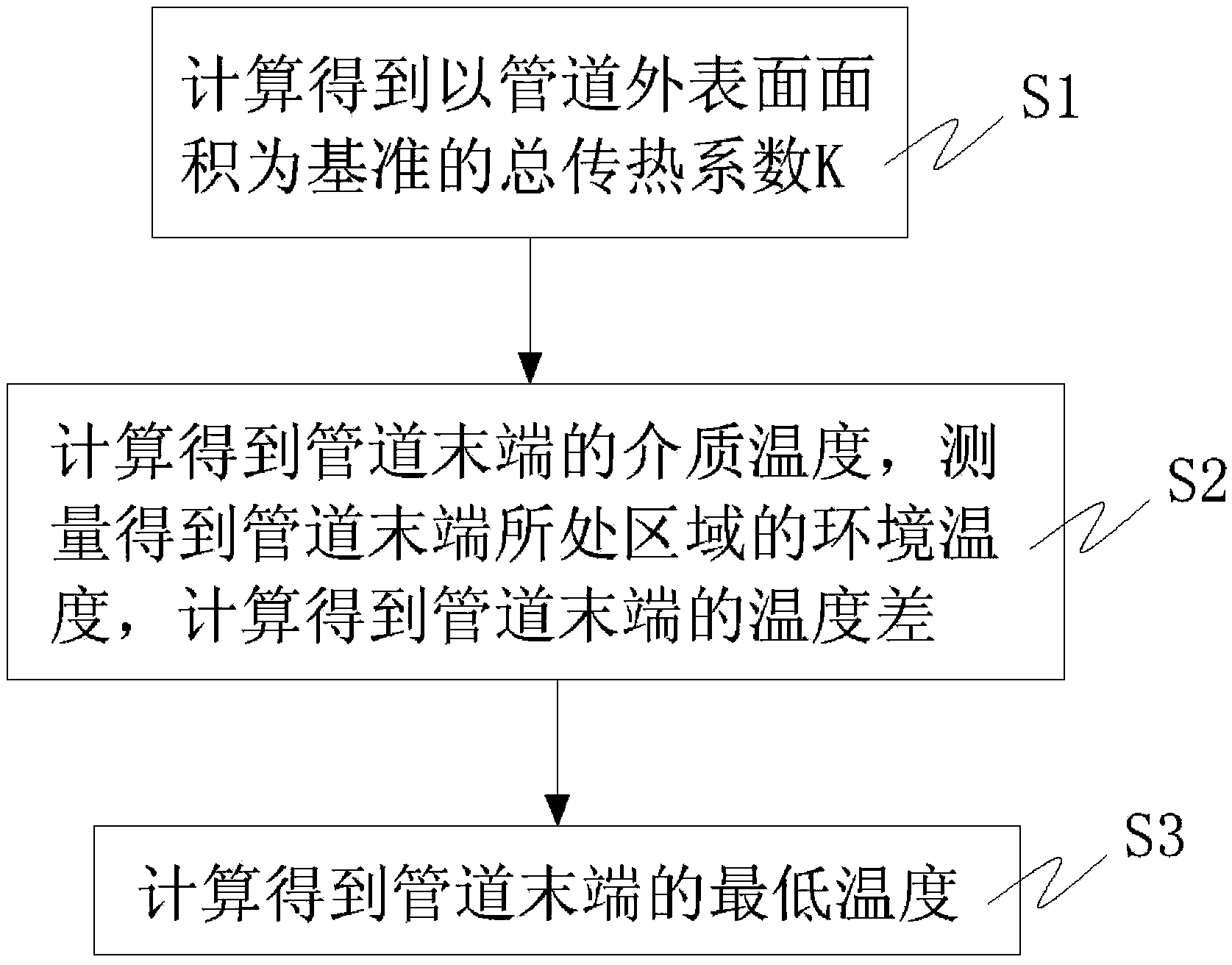
[0048] This embodiment provides a method for measuring the minimum wall temperature of exposed oil and gas pipelines, see figure 1 and figure 2 The measurement method consists of the following three steps:

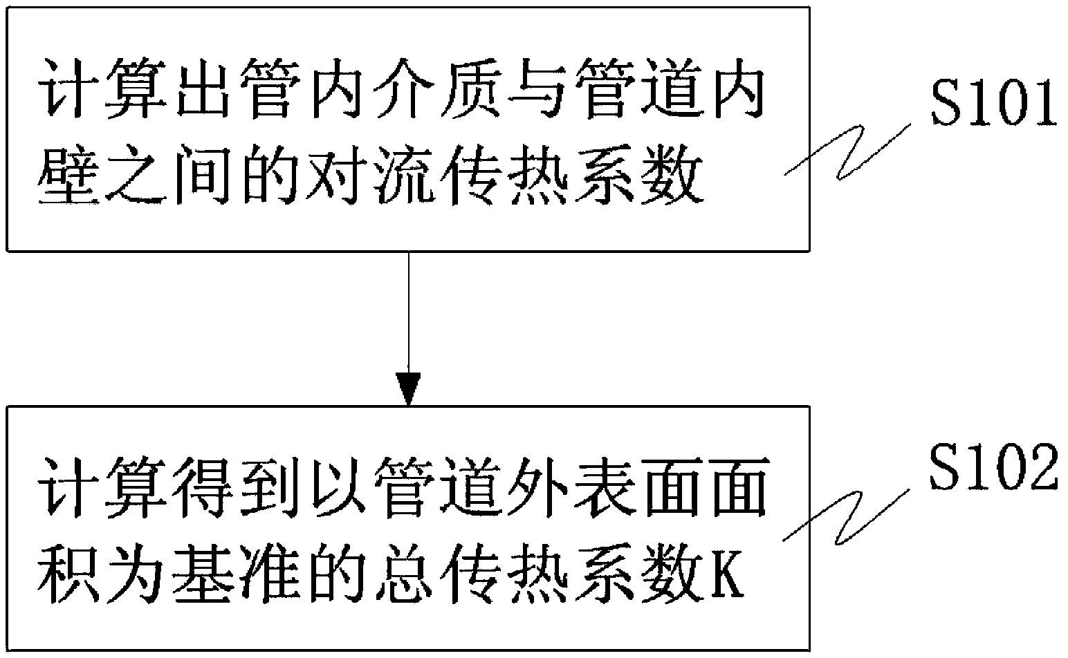
[0049] S1. Calculate the total heat transfer coefficient K based on the outer surface area of ​​the pipeline (unit: W / m2 °C);

[0050] S2. Calculate the medium temperature t at the end of the pipeline 2 (unit: °C), the ambient temperature t of the area where the end of the pipe is located is measured e (unit: ℃), using the medium temperature t at the end of the pipeline 2 Subtract the ambient temperature t in the area where the end of the pipe is located e Get the temperature difference Δt at the end of the pipe (unit: °C): Δt=t 2 -t e ;

[0051] S3. Use formula (1) to calculate the minimum wall temperature t at the end of the pipe min (Unit: °C):

[0052] t min = t e +KΔt / α o (1)

[0053] In formula (1), α o (Unit: W / m2 °C) is the conve...

Embodiment 2

[0069] This embodiment provides a method for measuring the minimum pipe wall temperature of an exposed oil and gas pipeline. The principle of the measurement method in this embodiment and the specific formula used are the same as those provided in Embodiment 1. This measurement method takes a 1000m exposed gas pipeline with a specification of φ610×20mm and operates at an ambient temperature of -40°C as an example, and details the engineering calculation steps of its minimum wall temperature as follows:

[0070] In the first step, query or measure to determine the following basic parameters: the inner diameter of the pipe d i =0.57m, pipe outer diameter d o =0.61m, pipe length x=1000m, steel pipe material heat transfer coefficient λ=16.27W / m °C, gas mass flow rate in the pipe M=6.626kg / s, gas viscosity in the pipe μ f =1.087×10⁻⁵kg / m s, constant pressure specific heat capacity C of the gas in the tube pf =2222J / kg °C, heat transfer coefficient of gas in the tube λ f =0.0332W...

Embodiment 3

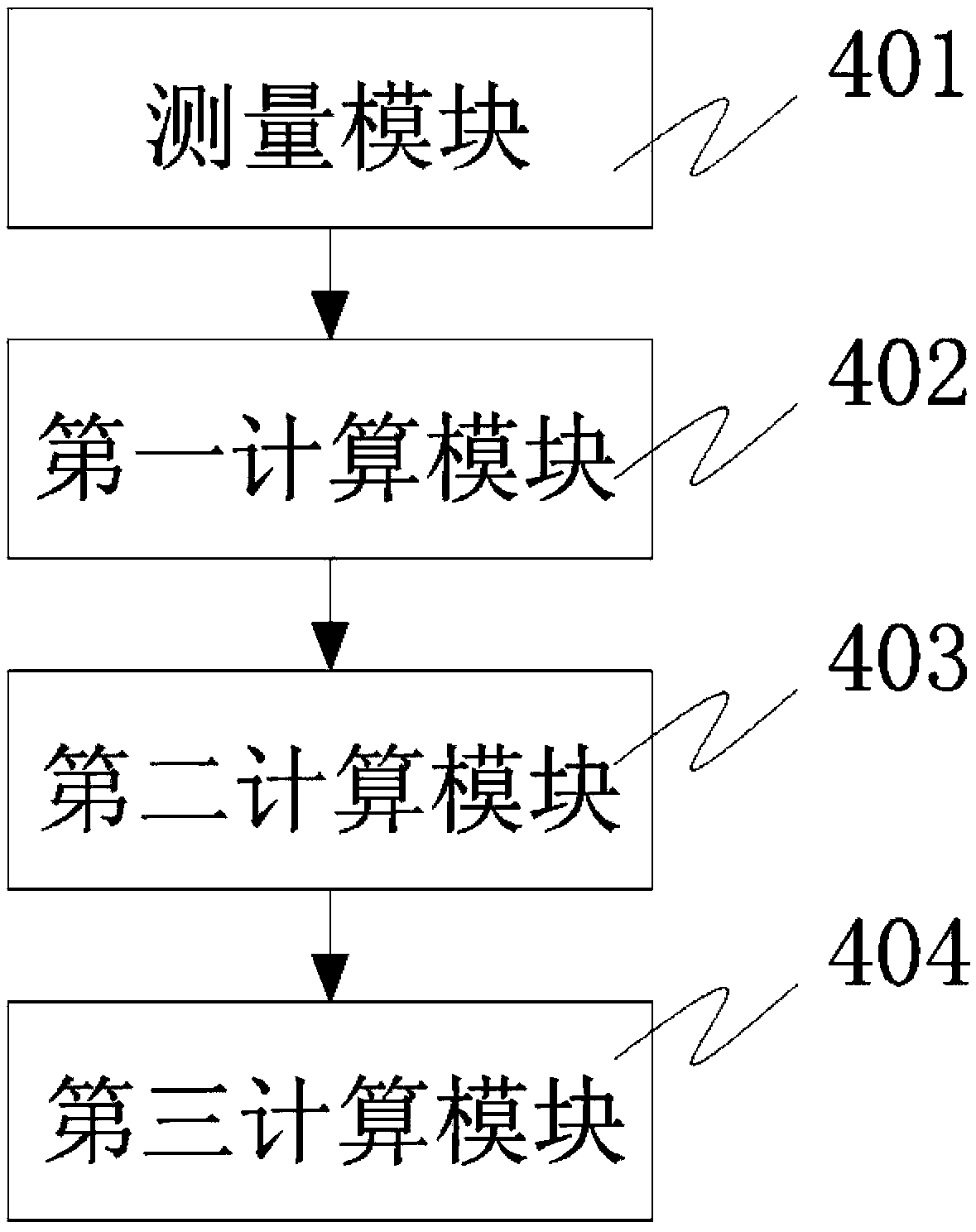
[0089] This embodiment provides a measuring device for the lowest pipe wall temperature of exposed oil and gas pipelines, see image 3 , the device consists of:

[0090] The measurement module 401 is used to measure the ambient temperature t of the area where the end of the pipeline is located e ;

[0091] The first calculation module 402 is used to calculate the total heat transfer coefficient K based on the outer surface area of ​​the pipeline;

[0092] The second calculation module 403 is used to calculate the medium temperature t at the end of the pipeline 2 , according to the measured ambient temperature t of the area where the end of the pipe is located e , using the medium temperature t at the end of the pipeline 2 Subtract the ambient temperature t in the region where the end of the pipe is located e Get the temperature difference Δt at the end of the pipe;

[0093] The third calculation module 404 is used to calculate according to the formula t min = t e +KΔt / ...


PUM


Abstract

The invention discloses a bared oil-gas pipeline minimum pipe wall temperature measuring method. The measuring method comprises the following steps: the first step in which the total heat transfer coefficient K by taking the area of the outer surface of the pipeline as the reference is calculated; the second step in which the medium temperature t2 at the tail end of the pipeline is calculated, the environment temperature te of the region at which the tail end of the pipeline is located is measured, and the environment temperature te of the region at which the tail end of the pipeline is located is subtracted from the medium temperature t2 at the tail end of the pipeline to obtain the temperature difference delta t at the tail end of the pipeline; and the third step in which the minimum wall temperature tmin at the tail end of the pipeline is calculated through the formula described in the description. According to the technical scheme of the invention, six principal factors influencing the bared steel tube minimum wall temperature in the low-temperature environment, including the environment temperature, the medium temperature, the environment wind speed, the conveying flow, the pipeline specification and the pipeline length are taken into account comprehensively, the estimation result of the minimum wall temperature is accurate and reliable, less difference exists between the estimation result and the wall temperature that measured practically, the accuracy of the method is higher than the accuracy of other engineering estimation methods, the accuracy of the method is equivalent to the accuracy of the numerical calculation method, and the method is simpler and more convenient than the numerical calculation method.

Description

technical field [0001] The invention relates to the technical field of engineering calculation of pipeline wall temperature, in particular to a method for measuring the minimum wall temperature of an exposed oil and gas pipeline, which is mainly used for measuring and calculating the minimum wall temperature of an exposed oil and gas pipeline in a low temperature environment. The invention also relates to a measuring device for the lowest pipe wall temperature of an exposed oil and gas pipeline. Background technique [0002] Oil and gas pipelines in low temperature environments and in the field are generally laid below the ground surface, but pipelines in relay stations, transfer stations, and maintenance stations are usually laid above the ground. However, due to technological reasons, some station pipelines The outer surface has no insulation layer and is directly affected by the low temperature environment. The toughness of pipes decreases at low temperature. When the te...

Claims


Application Information

Patent Timeline
IPC IPC(8): G01K11/00G01N25/20
Inventor 王海涛田伟冯耀荣吉玲康刘迎来张广利
Owner BC P INC CHINA NAT PETROLEUM CORP
Why Eureka
Try Eureka