Stepless compensating device and method

A compensation device and stepless technology, applied in reactive power compensation, reactive power adjustment/elimination/compensation, etc., can solve the problems of low cost performance and large user investment, and achieve the effects of high cost performance, accelerated response speed, and advanced technology

Inactive Publication Date: 2014-06-04
SHARESUN ELECTRICAL LIMITED BY SHARE
View PDF4 Cites 7 Cited by
  • Summary
  • Abstract
  • Description
  • Claims
  • Application Information

AI Technical Summary

Problems solved by technology

For a slightly larger power supply system, multiple modules need to be paralleled for compensation, the user has invested a lot, and the cost performance is too low

Method used


Image

  • Stepless compensating device and method
  • Stepless compensating device and method

Examples


Embodiment 1

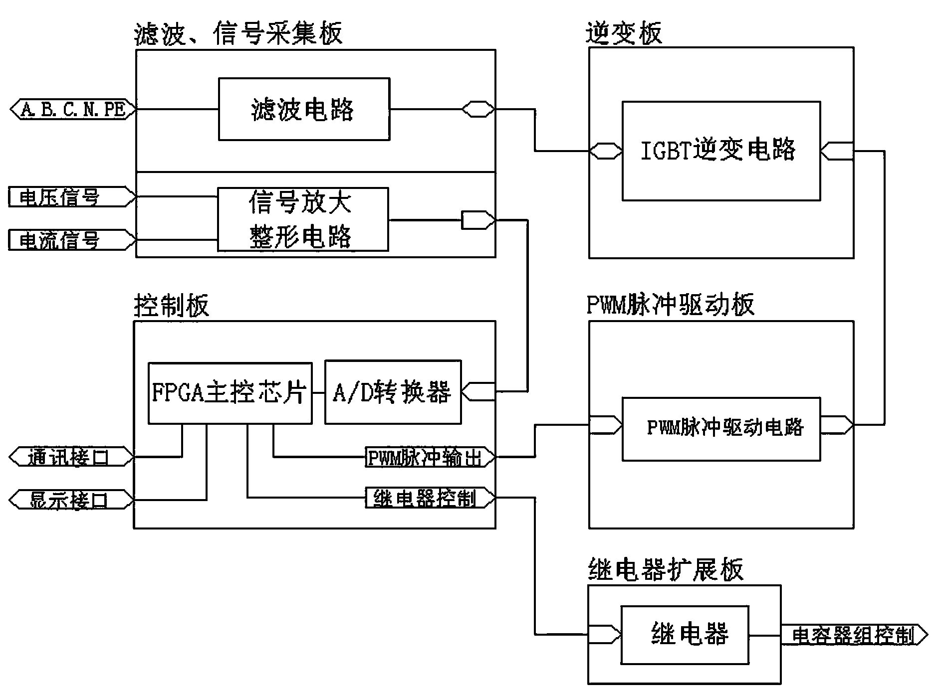
[0034] like figure 1 , figure 2 As shown, a stepless compensation device is mainly composed of the following components:

[0035] Filtering and signal acquisition board: it is mainly composed of a filter circuit and a signal amplification and shaping circuit. Used to receive the grid voltage signal and current signal and amplify and shape the signal;

[0036] Inverter board: mainly composed of IGBT inverter circuit, connected with filter circuit, used for the conversion between DC and AC;

[0037] Control board: mainly composed of FPGA main control chip, the FPGA main control chip is also connected to the A / D conversion chip, the A / D conversion chip is connected to the signal amplification and shaping circuit, and the control board is used to receive voltage and current signals And output commands to send control information;

[0038] PWM pulse drive board: mainly composed of PWM pulse drive circuit, connected with FPGA main control chip and IGBT inverter circuit, used to...

Embodiment 2

[0042] In order to better realize the present invention, it is convenient to switch to other equipment when reaching the set capacity, such as figure 1 As shown, on the basis of Embodiment 1, this embodiment further includes a relay expansion board, the relay expansion board is mainly composed of relays, and the relays are connected to the FPGA main control chip. When the reactive power of the load is greater than the set compensation capacity of the compensation device, by using the relay output, other compensation equipment can be used to reduce the output current of the compensation device. Other parts of this embodiment are the same as those of Embodiment 1, and will not be repeated here.

Embodiment 3

[0044] In order to better realize the present invention, this embodiment is based on Embodiment 2, and the relay is also connected to the capacitor bank. By adopting the way of connecting the relay and the capacitor bank, the capacitor bank can be used as a group switching, and the output reactive capacity can realize the connection between the device and the traditional equipment, thereby increasing the scope of application of the device. Other parts of this embodiment are the same as those of Embodiment 2, and will not be repeated here.


PUM


Abstract

The invention discloses a stepless compensating device which mainly comprises a filter, a signal collecting plate, an inversion plate, a control plate and a PWM pulse driving plate. Meanwhile, the invention discloses a stepless compensating method. An FPGA chip is used as a core element, a real-time data collecting technology and a dynamic tracking technology are used for monitoring the electric energy quality of a power distribution system in real time, through a monitoring system, a series of electric energy quality data such as system voltages, frequency, loading currents, THDi, THDu, voltage waveform, current waveform, stepless compensating device output current magnitude and waveform can be checked in real-time, the idle current magnitude output by the device is changed continuously through an inversion circuit, quick and continuous idle power compensating is achieved, through the method, idle currents are compensated timely, and the whole structure has the advantages of being scientific, reasonable, advanced in technology, timely in compensating, high in stability, high in cost performance and the like.

Description

technical field [0001] The invention relates to a fast continuous reactive power compensation device and a method for stepless compensation using the device, specifically, a stepless compensation device and a stepless compensation method. Background technique [0002] Traditional reactive power compensation devices use power electronics and single-chip microcomputer control technology to realize automatic control of parallel capacitors and realize switching control of parallel capacitor banks. The switching devices of traditional compensation devices are contactors or thyristors, and the output channels can be freely assembled. However, the switching compensation method of contactors and thyristors is switched in groups. The reactive power output capacity is stepped, and the compensation capacity cannot be continuously adjusted. , it is difficult to achieve a complete balance with the reactive power of the system, and it is easy to cause over-compensation or under-compen...

Claims


Application Information

Patent Timeline
Patent Type & Authority Applications(China)
IPC IPC(8): H02J3/18
CPCY02E40/30
Inventor 夏文红
Owner SHARESUN ELECTRICAL LIMITED BY SHARE
Why Eureka
Try Eureka