Method for logically controlling combined chopped waves of power switch devices of switched reluctance motor

A technology of power switching devices and switched reluctance, which is applied in the direction of electronically commutated motor control, control systems, electrical components, etc., can solve the problems of uneven heating of power switching devices and reduce power switching devices, so as to prolong life and reduce switching costs. Stress, the effect of solving uneven heating

Inactive Publication Date: 2014-06-04
浙江仕迈电机有限公司
View PDF4 Cites 7 Cited by
  • Summary
  • Abstract
  • Description
  • Claims
  • Application Information

AI Technical Summary

Problems solved by technology

[0003] In view of the above defects, the present invention provides a switched reluctance motor power switching device combined chopping logic control method, which can solve the problem of uneven heating of the power switching device, thereby reducing the switching stress of the power switching device and prolonging the life of the power switching tube

Method used


Image

  • Method for logically controlling combined chopped waves of power switch devices of switched reluctance motor
  • Method for logically controlling combined chopped waves of power switch devices of switched reluctance motor
  • Method for logically controlling combined chopped waves of power switch devices of switched reluctance motor

Examples


Embodiment Construction

[0014] The present invention will be further described below in conjunction with the accompanying drawings and specific embodiments.

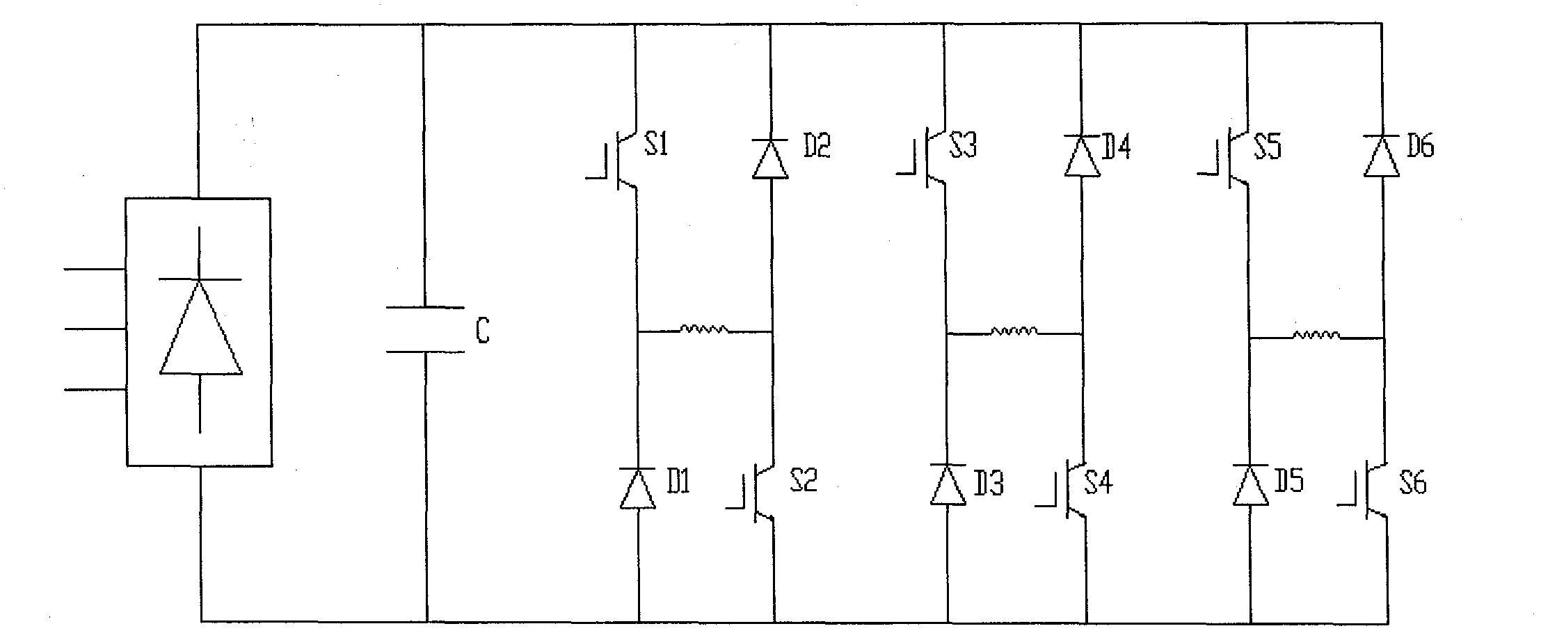
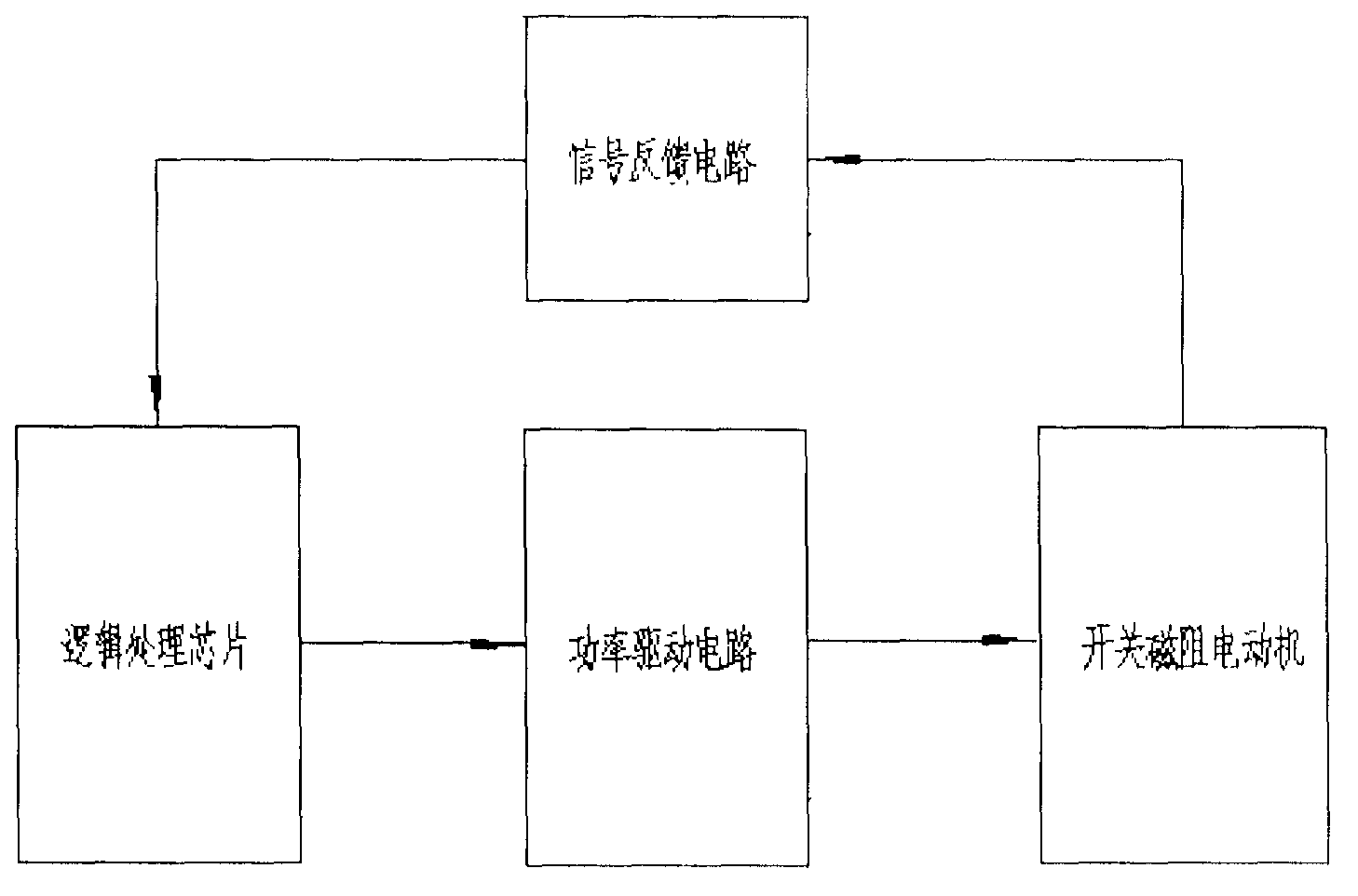
[0015] In the switching reluctance motor power switching device combined chopping logic control method of the present invention, at first a combined chopping logic control circuit is designed, such as figure 1 As shown, the combined chopping logic control circuit includes a signal bow 'feedback circuit connected with the switched reluctance motor, and the said double bow 'feedback circuit is connected with a logic processing chip and a power drive circuit in turn; as figure 2 As shown, in the power drive circuit, the three-phase power supply input is provided to the power switch tube after bridge rectification and filter capacitor C, and the power switch tube forms an asymmetric bridge topology circuit structure, and each phase is composed of two power switch tubes 1. Two diodes and motor windings are connected in series to form upper and 'two...


PUM


Abstract

The invention discloses a method for logically controlling combined chopped waves of power switch devices of a switched reluctance motor. A combined chopped wave logical control circuit adopted in the method comprises a signal feedback circuit, a logical processing chip and a power drive circuit, wherein the logical processing chip and the power drive circuit are connected in sequence. A power switch tube set in the power drive circuit is of an asymmetric bridge type topological circuit structure. Each phase is of a structure of an upper bridge arm and a lower bridge arm, wherein the structure is composed of two power switch tubes, two diodes and a motor winding in series connection. When the current of the switched reluctance motor is increased, the power switch tubes of the upper bridge arm and the lower bridge arm are switched on simultaneously; when the current is reduced, one power switch tube is switched off and the other power switch tube is switched on. According to the method for logically controlling the combined chopped waves of the power switch devices of the switched reluctance motor, consumption of a switch is evenly distributed to the two switch devices on one phase, the use frequency of the switch devices is balanced, so that the problem that the power switch devices emit heat unevenly is solved, the switching stress of the power switch devices is reduced, and the service life of the power switch tubes is prolonged.

Description

technical field [0001] The invention relates to a switching reluctance motor power switching device combined chopping logic control method, which belongs to the technical field of optimal control of switched reluctance motors. Background technique [0002] At present, the traditional current chopping control (CCC) method in the current control of the switched magneto-cathode motor achieves the purpose of controlling the output current of the motor by adjusting the turn-on and turn-off time ratio of a power switch tube. When the motor current is limited, the loss of the power switch tube increases with the increase of the switching frequency, resulting in uneven heating of the power switch tube within a certain period of time. At the same time, the voltage change rate dv / dt on the power switch tube increases significantly with the switching frequency during the switching process, which increases the voltage stress of the power switch tube and affects the life of the power swi...

Claims


Application Information

Patent Timeline
Patent Type & Authority Applications(China)
IPC IPC(8): H02P6/00
Inventor 苗骞郭振
Owner 浙江仕迈电机有限公司
Why Eureka
Try Eureka