Acoustic structure with passive vibrating diaphragm unit

A passive diaphragm and acoustic structure technology, applied in the transducer shell/cabinet/stand and other directions, can solve the problems of limited speaker design and inability to take into account the acoustic performance of the speaker system, and achieve good bass effect, low vibration, good application sexual effect

Inactive Publication Date: 2014-06-04
李世煌
View PDF5 Cites 14 Cited by
  • Summary
  • Abstract
  • Description
  • Claims
  • Application Information

AI Technical Summary

Problems solved by technology

Therefore, the design of the speaker system often has a unique threshold, not just considering its appearance
If we consider its appearance, structure, etc., we often cannot take into account the acoustic performance of the speaker system.
Therefore, for a certain electromagnetic speaker with excellent performance, its speaker design is often limited, and it cannot quickly adapt to the appearance requirements of many different application environments.

Method used


Image

  • Acoustic structure with passive vibrating diaphragm unit
  • Acoustic structure with passive vibrating diaphragm unit
  • Acoustic structure with passive vibrating diaphragm unit

Examples


Embodiment 1

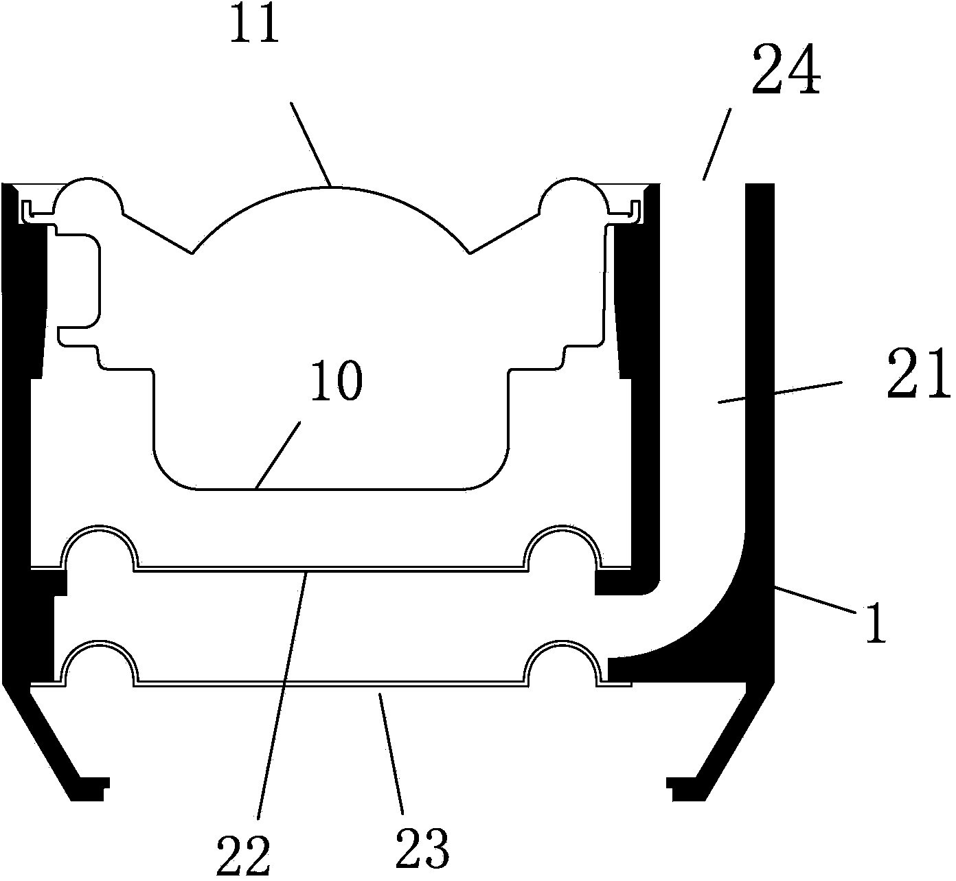
[0066] Such as figure 1 , the present embodiment provides an audio radiation module, which includes an annular casing 1; a speaker unit 10, the speaker unit 10 is installed in the annular casing 1, and the sound cone 11 of the speaker unit 10 is connected to the annular The shell 1 is connected and exposed to the air environment; there is a radiation port 24 on the side of the circular shell 1 connected to the sound cone 11 of the speaker unit 10; the radiation port 24 is located on the surface of the sound cone 11 of the speaker unit 10 Periphery; Passive diaphragm unit 22 and 23, described passive diaphragm unit 22 and 23 are positioned at the rear of described loudspeaker unit 10, coaxially placed with described loudspeaker unit 10; Described passive diaphragm unit 22 and 23 and annular The shells 1 are connected by elastic rings 221 and 231 . The side of the speaker unit 10 is provided with a radiation pipe 21 , and one end of the radiation pipe 21 is connected to the rad...

Embodiment 2

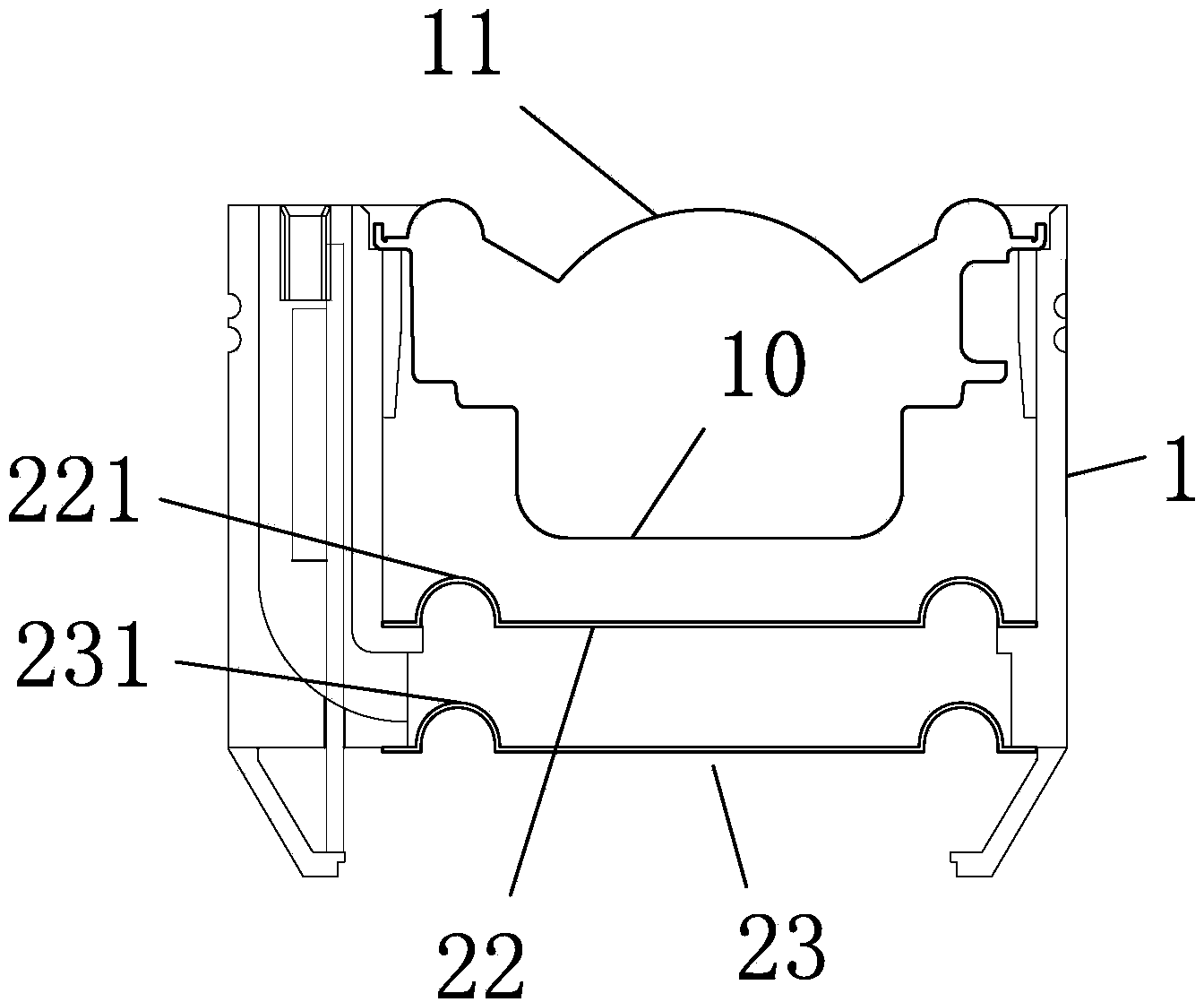
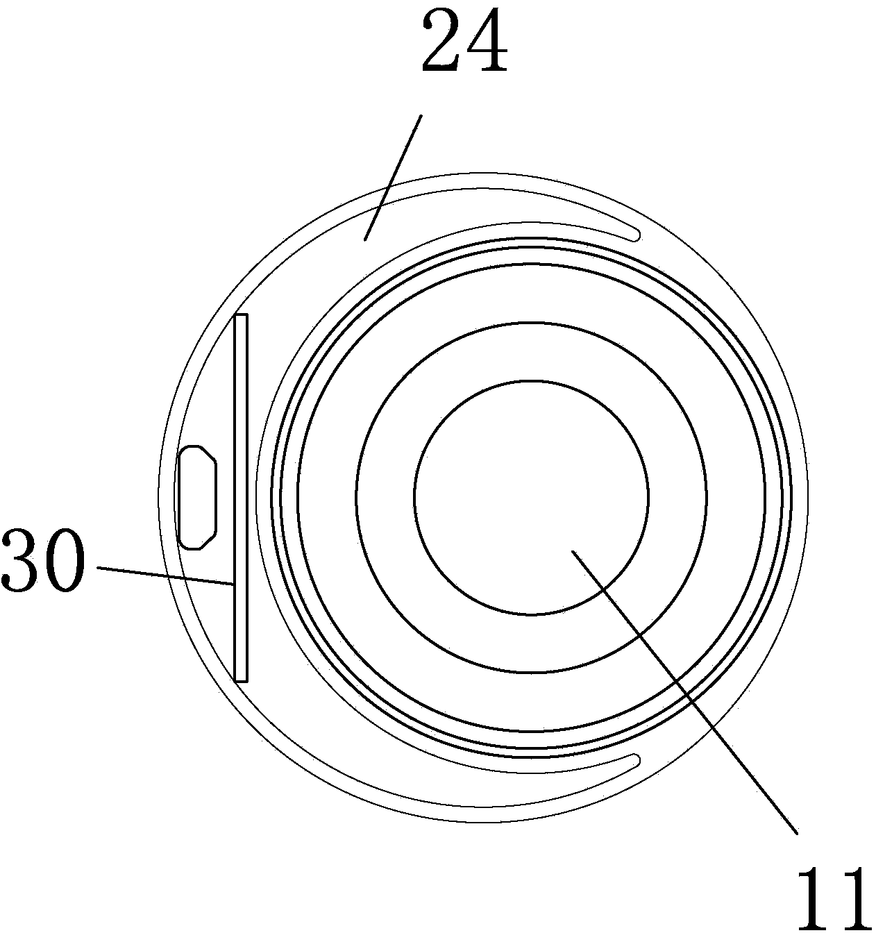
[0073] refer to figure 2 , image 3 , the structure of this embodiment is similar to that of Embodiment 1, the difference is that the cross-section of the radiant tube 21 of this embodiment is "C"-shaped, covering the outer periphery of the cross-section of the sound cone 11, which is helpful for the speaker unit 10 side The circuit board 30 is hidden, so that various active module solutions, such as amplifiers, frequency dividers, etc., can be constructed.

[0074] The passive diaphragm unit of this embodiment and the elastic rings connected between 22, 23 and the annular shell 1 have structures in the same direction, as Figure 8 As shown, the directions of the elastic rings 221 and 231 are the same; in actual situations, the elastic force of the elastic rings 221 or 231 is not equal when the radiating unit 22 or 23 goes up or down respectively, and this structure makes the passive diaphragm units 22 and 23 irrespective of Whether it is expansion or contraction, the elast...

Embodiment 3

[0076] Such as Figure 4 As shown, the three-dimensional schematic view of the shell of the second embodiment of the present invention.

[0077] The structure of the present embodiment is similar to that of the first embodiment, the difference is that the cross-sectional area of ​​the radiant tube 21 of the second embodiment is constant, and it is a pipeline of the same diameter, while the radiant tube 21 of the present embodiment is connected to the atmosphere from the end The radiation opening 24 has an expanding edge 29, making it a gradually expanding shape. The radiant tube 21 of this form has the characteristics of small acoustic resistance, and at the same time has the effect of amplifying the sound waves it collects, further improving the sound generation performance of the whole module.


PUM


Abstract

The invention provides an acoustic structure with a passive vibrating diaphragm unit. The acoustic structure comprises a loudspeaker unit, the passive vibrating diaphragm unit and a radiant tube, wherein the passive vibrating diaphragm unit is located at the back of a sound cone of the loudspeaker unit, the radiant tube is arranged on the side face of the loudspeaker unit, one end, exposed in air, of the radiant tube is located on the periphery of the sound cone of the loudspeaker unit and is consistent with the loudspeaker unit in orientation, the passive vibrating diaphragm unit is driven by the loudspeaker unit to vibrate, acoustic waves generated through vibration of the passive vibrating diaphragm unit are emitted through the radiant tube and a radiation port and reach the approximately same sound production point with the loudspeaker unit, the sound production effect of gamut approximate point sound sources is achieved, the phase difference of sound production of the sound cone of the loudspeaker unit and sound production of the passive vibrating diaphragm unit is reduced, and the sound positioning aspect is greatly enhanced. The invention further provides a compact type voice frequency radiation module with the structural design and a loudspeaker box with the structural design.

Description

technical field [0001] The invention relates to an acoustic structure design, in particular to an acoustic structure using a passive diaphragm unit. Background technique [0002] When the speaker unit vibrates due to electromagnetic drive, the wavelength of the low-frequency sound waves is larger than the size of the speaker, causing the low-frequency sound waves at the front and back of the speaker to cancel each other out. Commonly used inverters are inverter tubes or passive diaphragm units. For the structure using the passive diaphragm unit, because the passive diaphragm unit is often placed on one side of the speaker unit or the box, it will passively vibrate after receiving the vibration of the speaker unit, and then emit sound waves. The disadvantage of this structure is that the sound waves emitted by the passive diaphragm unit and the speaker unit have different synthesis effects (with phase difference) depending on the listening position, resulting in distortion, ...

Claims


Application Information

Patent Timeline
Patent Type & Authority Applications(China)
IPC IPC(8): H04R1/02
Inventor 李世煌
Owner 李世煌
Why Eureka
Try Eureka