
Permanent magnet magnetic separation column

A technology of magnetic separation column and permanent magnetic system, which is applied in the field of magnetic separation column, can solve problems such as unstable operation, inconvenient installation, and large water consumption, and achieve the effects of stable and reliable operation, simple structure, and low water consumption

Active Publication Date: 2014-06-11
潍坊隆利重机有限公司
View PDF6 Cites 15 Cited by
  • Summary
  • Abstract
  • Description
  • Claims
  • Application Information

AI Technical Summary

Problems solved by technology

In actual production, the existing electromagnetic magnetic separation column still has the following disadvantages: 1) Due to the defects of structure and design principle, it consumes a lot of water and has a lot of running tails, which leads to serious waste of resources and energy; it is large in size and inconvenient to install, etc.; 2) Due to the use of electromagnets as magnetic force generating components, many electrical components are required, the control is complicated, electrical failures are prone to occur, and the operation is unstable

Method used


Image

  • Permanent magnet magnetic separation column
  • Permanent magnet magnetic separation column
  • Permanent magnet magnetic separation column

Examples


Embodiment Construction

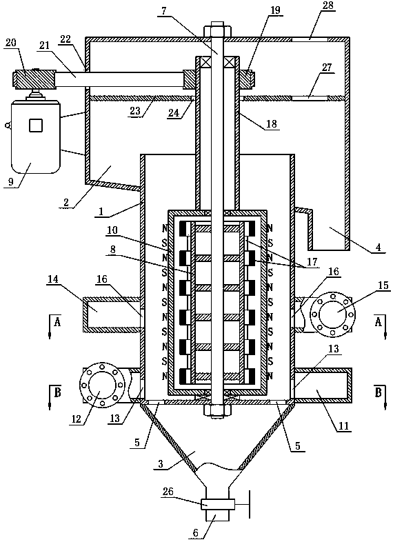
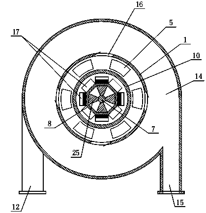
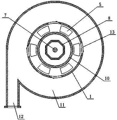
[0020] Referring to the accompanying drawings, the permanent magnet magnetic separation column of the present invention includes an outer cylinder 1 with an open top, an overflow tank 2 installed on the top of the outer cylinder 1 and a concentrate bucket 3 installed at the bottom of the outer cylinder 1, the outer cylinder 1 The top end passes through the middle part of the bottom wall of the overflow box 2, and the bottom wall of the overflow box 2 is provided with a tailings port 4. Wherein, in order to facilitate the discharge of impurities, the bottom wall of the overflow box 2 is inclined, and the tailings port 4 is set at the relatively low end of the bottom wall of the overflow box 2 . The bottom wall of the outer cylinder 1 is provided with a concentrate leak hole 5 for communicating with the concentrate hopper 3 , and the bottom of the concentrate hopper 3 is provided with a concentrate outlet 6 on which a concentrate valve 26 is installed. The outer cylinder body 1 ...


PUM


Abstract

The invention relates to a permanent magnet magnetic separation column. The permanent magnet magnetic separation column comprises an outer cylinder, an overflow tank and a concentrate bucket, wherein the top end of the outer cylinder penetrates through the middle part of the bottom wall of the overflow tank, a tailing port is formed in the bottom wall of the overflow tank, a concentrate leaking hole which is used for being communicated with the concentrate bucket is formed in the bottom wall of the outer cylinder and a concentrate outlet is formed in the bottom of the concentrate bucket; a center shaft is fixedly installed in the outer cylinder, a permanent magnet magnetic system is fixedly sheathed at the lower part of the center shaft and a rotary drum which is sheathed outside an inner cylinder and is driven by a motor is rotatably installed on the center shaft; an annular water tank is sheathed at the bottom of the outer cylinder and a plurality of inner flushing ports which are communicated with the water tank are annularly arranged at intervals on the wall of the outer cylinder; an annular ore feeding tank is sheathed at the middle-to-lower part of the outer cylinder and a plurality of inner ore feeding ports which are communicated with the ore feeding tank are annularly arranged at intervals on the wall of the outer cylinder. The permanent magnet magnetic separation column has the advantages of simple structure, high operation stability and reliability, small water consumption and less tailing run-out.

Description

technical field [0001] The invention relates to the field of magnetic separation columns, in particular to a permanent magnet magnetic separation column. Background technique [0002] Silicon and other non-metallic mineral impurities doped in iron powder will affect the taste of iron powder. According to the phenomenon of magnetic agglomeration of fine iron powder in a weak magnetic field, a magnetic agglomeration machine appeared on the market earlier, which has a certain effect on improving the grade. , but its water consumption is large and its efficiency is low. In addition, due to the limitation of production conditions, its working state is unstable, so it is rarely used now. At present, the commonly used equipment to improve the taste of iron concentrate powder is electromagnetic magnetic separation column, which belongs to a kind of electromagnetic weak magnetic field magnetic re-separator, with magnetic force as the main force and gravity as the auxiliary force. It ...

Claims


Application Information

Patent Timeline
Patent Type & Authority Applications(China)
IPC IPC(8): B03B7/00B03C1/02
Inventor 刘兴魁
Owner 潍坊隆利重机有限公司
Learn More