Double-sleeper tamping device

A technology of beams and end plates, which is applied in the field of tamping vehicles for railway maintenance machinery, can solve the problems of not being able to apply tamping operations at the same time, and achieve the effects of being conducive to on-site maintenance, long weld seams, and convenient for picks

Active Publication Date: 2014-06-11
CHANGZHOU RUITAI ENG MASCH CO LTD +1
View PDF8 Cites 7 Cited by
  • Summary
  • Abstract
  • Description
  • Claims
  • Application Information

AI Technical Summary

Problems solved by technology

However, the tamping device cannot be applied to other tamping

Method used


Image

  • Double-sleeper tamping device
  • Double-sleeper tamping device
  • Double-sleeper tamping device

Examples


Embodiment Construction

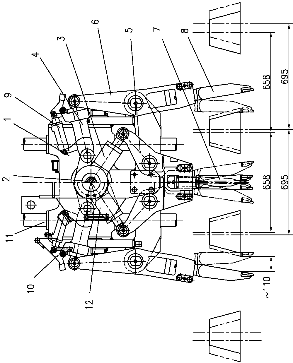
[0055] Such as figure 1 As shown, the DC-32C tamping device of the prior art includes a box body 1, a vibrating shaft 2, an inner clamping oil cylinder 3, an outer clamping oil cylinder 4, an inner pick arm 5, an outer pick arm 6, an inner stamping pick 7, an outer Tamper pick 8, cylinder 9, block 10, guide post 11, supporting arm and oil tank 12. When the hydraulic motor drives the vibrating shaft 2 to rotate, its eccentric part produces eccentric movement, which is transmitted to the inner tamper 7 and outer tamper 8 through the inner clamping cylinder 3, outer clamping cylinder 4, inner pick arm 5, outer pick arm 6 , so that the pick palms of the inner pounding pick 7 and the outer pounding pick 8 are forced to vibrate slightly. The clamping force is generated by the action of the hydraulic system on the inner clamping cylinder 3 and the outer clamping cylinder 4, and the clamping force and movement pass through the piston rods of the inner clamping cylinder 3 and the oute...


PUM


Abstract

The invention discloses a double-sleeper tamping device. The double-sleeper tamping device comprises a box body, a vibrating shaft, an inner clamping oil cylinder, an outer clamping oil cylinder, an inner picking arm, an outer picking arm, an inner side tamping pick, an outer side tamping pick, an air cylinder, check blocks, a guide pillar, and a supporting arm and oil tank assembly. The box body is at least formed by welding a middle body, a cross beam, end plates, outer supporting bosses, stop baffles and hanger plates. The distance between the center of an outer picking arm pin hole in the cross beam of the box body and the central line of the box body is equal to 600 mm +/- 20 mm. The supporting arm and oil tank assembly comprises a supporting arm, two oil tanks and a flywheel guard. The check blocks are arranged between the front end of a piston rod of the outer clamping oil cylinder and a cylinder cover of the outer clamping oil cylinder. The check blocks comprise fixed check blocks and reversible check blocks. Through the utilization of check blocks of different numbers, downward inserting position and clamping travel of the outer side tamping pick can be adjusted, and operation requirements of different sleeper intervals are met. The double-sleeper tamping device is reasonable in structure, and can not only meet station track operations, but also meet main track operations.

Description

technical field [0001] The invention relates to a railway road maintenance mechanical tamping vehicle, in particular to the structure of a tamping device. Background technique [0002] The tamping device is the main working device of the large-scale road maintenance machinery tamping vehicle. It is mainly used for tamping the ballast on both sides of the rail to improve the compactness of the ballast on the bottom of the pillow, and cooperates with the lifting device to eliminate the unevenness of the track and enhance the stability of the track. [0003] At present, the DC-32 and DCL-32 double-sleeper tamping vehicles widely used on my country's lines are mainly used for tamping operations on the main railway line, while the station line lines within the scope of railway stations have been ignored by people, and even some station lines It has been in disrepair for a long time and has become a bottleneck in the development of railway transportation. Therefore, it is of grea...

Claims


Application Information

Patent Timeline
IPC IPC(8): E01B27/20
Inventor 翁敏红王磊李可为夏春华吴海涛聂志镇王树海耿路峰李冬冬范佳
Owner CHANGZHOU RUITAI ENG MASCH CO LTD
Why Eureka
Try Eureka