Turbocharger heat insulation cover

A technology for turbochargers and heat shields, applied in the direction of machines/engines, engine components, mechanical equipment, etc., can solve the problems of high thermal stress on elastic folds, damage and fracture of superchargers, etc., to prolong service life, Reliable positioning and the effect of improving the working environment

Active Publication Date: 2014-06-11
HUNAN TYEN MACHINERY
View PDF5 Cites 1 Cited by
  • Summary
  • Abstract
  • Description
  • Claims
  • Application Information

AI Technical Summary

Problems solved by technology

The disadvantages of the above two heat shields are: the elastic flange on the heat shield is in line contact or point contact with the junction between the turbine box and the intermediate body. When the turbocharger is working, the elastic flange is subjected to a large thermal stress , prone to breakage and damage to the supercharger

Method used


Image

  • Turbocharger heat insulation cover
  • Turbocharger heat insulation cover
  • Turbocharger heat insulation cover

Examples


Embodiment 1

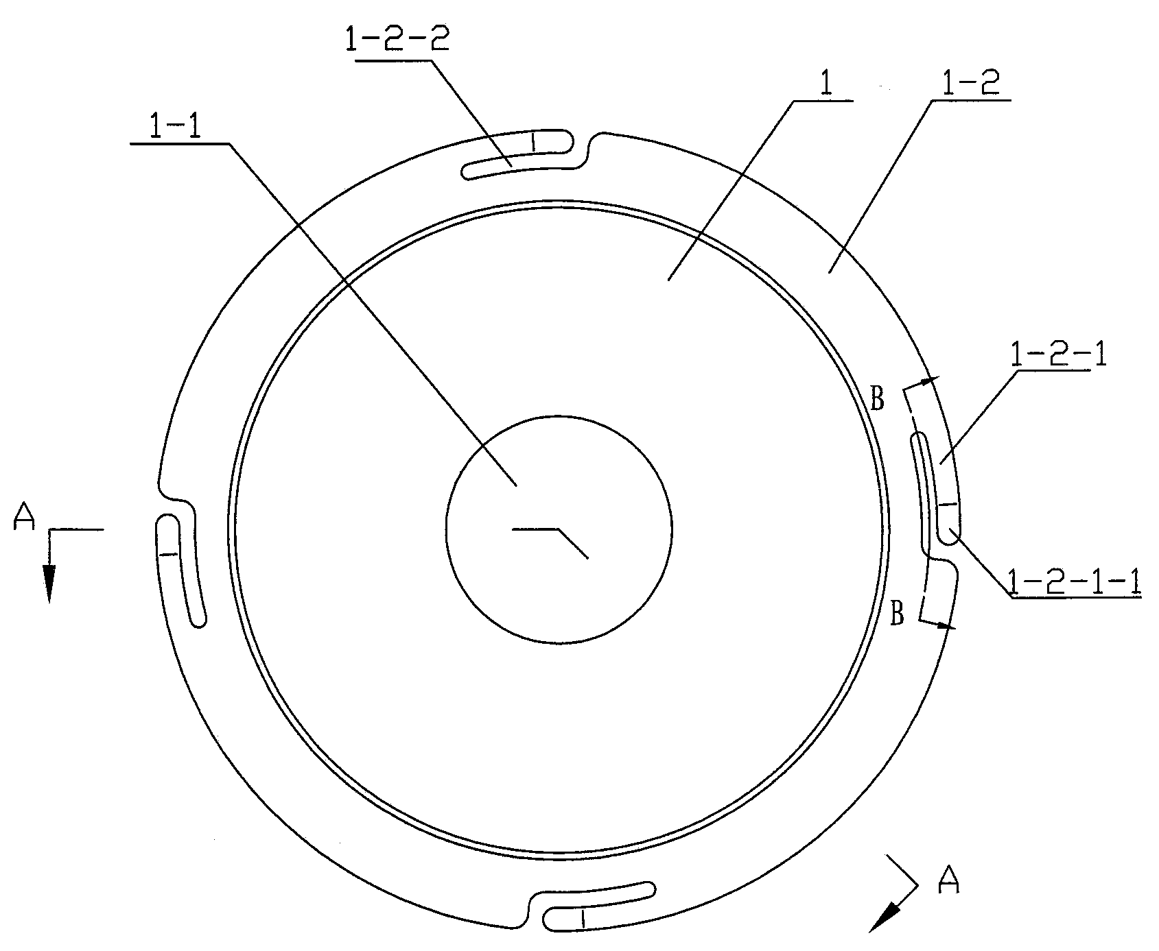
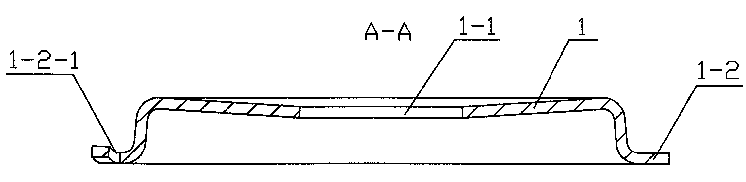
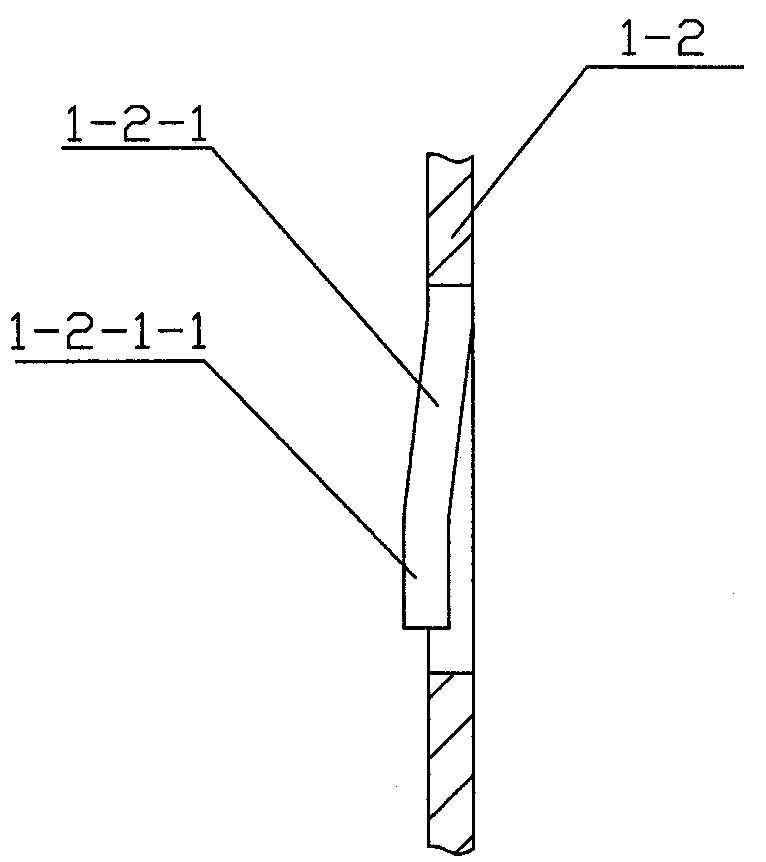
[0021] Embodiment 1. A heat shield for a turbocharger. The body of the heat shield 1 is an annular cover with a heat shield at one end and an opening at the other end. The center of the heat shield is provided with a central through hole. 1-1, the opening end of which is provided with a circle of flanging edges 1-2 turned outwards, the end plane of the flanging edge 1-2 is perpendicular to the axis line of the central through hole 1-1, and the edge of the flanging edge 1-2 There are four elastic tongue plates 1-2-1 protruding from the flange end plane, the elastic tongue plates 1-2-1 protrude toward the end with the heat insulation board, and the four elastic tongue plates 1-2-1 are uniform Arranged on the edge of the folded edge 1-2, the inner side of each elastic tongue plate 1-2-1 is provided with a strip-shaped arc-shaped insulating belt 1-2-2, and the top end of the elastic tongue plate 1-2-1 is bent Go out the pressing surface 1-2-1-1 parallel with the end plane of flang...

Embodiment 2

[0023] Embodiment 2. A heat shield for a turbocharger. The body of the heat shield 1 is an annular cover with a heat shield at one end and an opening at the other end. The center of the heat shield is provided with a central through hole. 1-1, the opening end of which is provided with a circle of flanging edges 1-2 turned outwards, the end plane of the flanging edge 1-2 is perpendicular to the axis line of the central through hole 1-1, and the edge of the flanging edge 1-2 There are six elastic tongues 1-2-1 protruding from the flanged end plane, the elastic tongues 1-2-1 protrude toward the end with the heat insulation board, and the six elastic tongues 1-2-1 are uniform Arranged on the edge of the folded edge 1-2, the inner side of each elastic tongue plate 1-2-1 is provided with a strip-shaped arc-shaped insulating belt 1-2-2, and the top end of the elastic tongue plate 1-2-1 is bent Go out the pressing surface 1-2-1-1 parallel with the end plane of flanging 1-2.

[0024] ...


PUM


Abstract

The invention provides a turbocharger heat insulation cover. A body of the heat insulation cover is an annular cover cap with one end provided with a heat insulation plate and the other end providedwith an opening, the center part on the heat insulation plate is provided with a center through hole, the opening end is provided with a circle of outwards flanged folding edge, the end plane of the folding edge is vertical to the axis line of the center through hole, the edge of the folding edge is provided with a plurality of elastic tongue plates projected out of the end plane of the folding edge, the elastic tongue plates are uniformly arranged on the edge of the folding edge, the inner side of each elastic tongue plate is provided with a stripped arc-shaped heat insulation belt, and a compression surface parallel to the end plane of the folding edge is formed at the top ends of the elastic tongue plates through folding and bending.

Description

technical field [0001] The invention relates to the technical field of turbochargers, in particular to a heat shield used on a turbocharger. Background technique [0002] The heat shield of the turbocharger is located at the junction of the turbine case and the intermediate body of the turbocharger, and is closely matched with the turbine case and the intermediate body. The function of the heat shield is to prevent the high heat of the engine exhaust passing through the turbine box from being excessively transferred to the intermediate body and the lubrication system containing high-speed rotating parts, and to protect multiple important parts of the supercharger from the influence of excessive temperature. Optimized Supercharger internal working environment. Under the development trend of the supercharger structure becoming more and more compact, it is very common for the turbine box and the intermediate body of the turbocharger to be connected by a clamp. surface, while ...

Claims


Application Information

Patent Timeline
Patent Type & Authority Applications(China)
IPC IPC(8): F01D25/08
Inventor 周峥李文军何光清邹祥
Owner HUNAN TYEN MACHINERY
Why Eureka
Try Eureka