Hydraulic pressurizing oil tank

A pressurized fuel tank and hydraulic technology, which is applied in the direction of fuel supply tank devices, fluid pressure converters, mechanical equipment, etc., can solve the problems of fuel tank cavitation, complex structure, poor boosting effect, etc., and achieve good boosting effect, The effect of high working reliability and simple structure

Inactive Publication Date: 2014-06-11
WUXI JINKAILI HYDRAULIC MACHINERY
View PDF0 Cites 15 Cited by
  • Summary
  • Abstract
  • Description
  • Claims
  • Application Information

AI Technical Summary

Problems solved by technology

The disadvantage of the traditional pressurized fuel tank is that the pressurized effect is not good

Method used


Image

  • Hydraulic pressurizing oil tank

Examples


Embodiment Construction

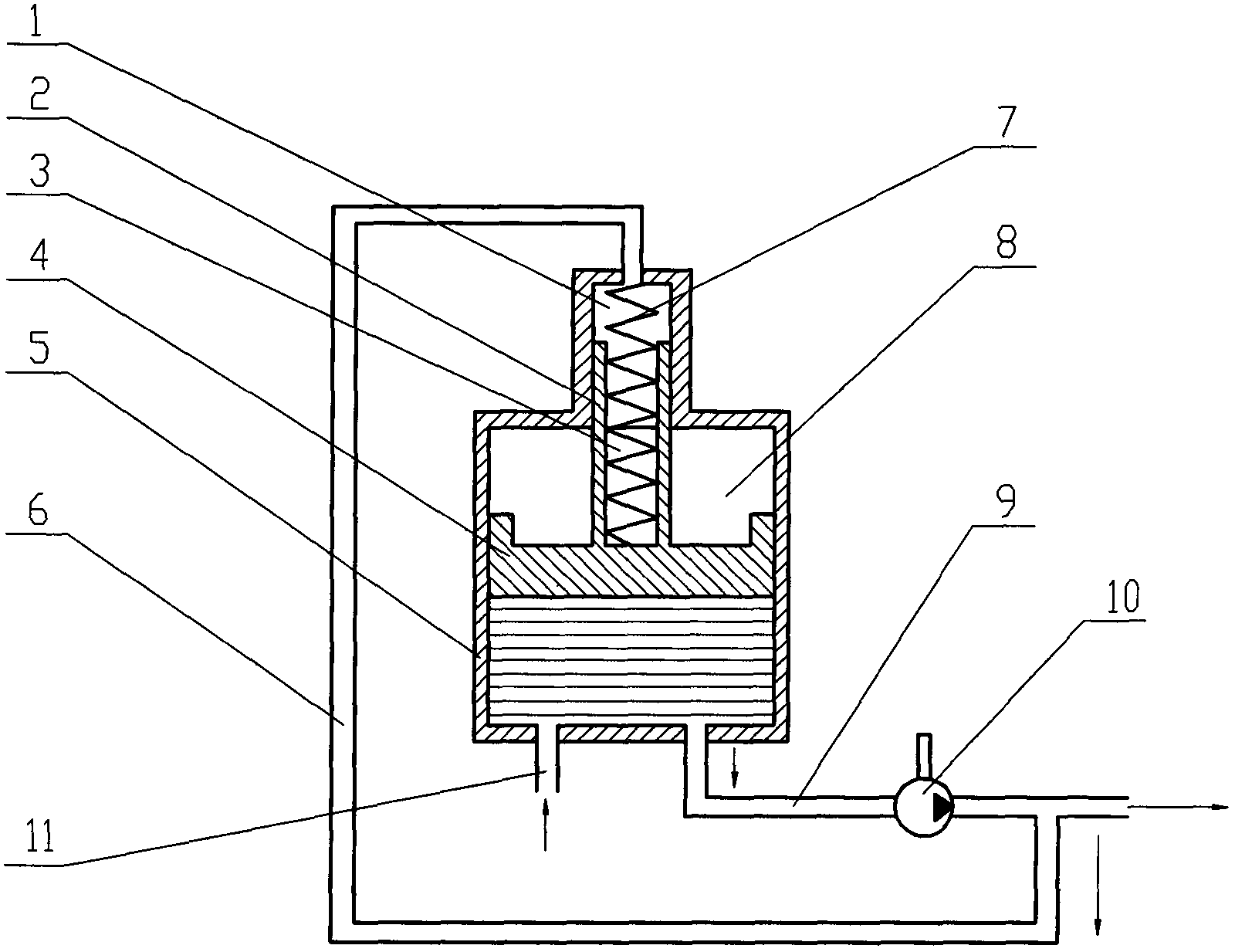
[0011] The specific embodiments of the present invention will be further described below in conjunction with the drawings.

[0012] see figure 1 , The present invention includes a box body 5, a piston 4 in the box body 5: the box body 5 has a first cavity 1 and a second cavity 8, the piston 4 is located in the second cavity 8, and the piston 4 is fixedly connected to the piston rod 2. The piston rod 2 is located in the first cavity 1, the piston rod 2 has an inner cavity 3, a spring 7 is connected in the inner cavity 3, and the spring 7 is fixedly connected with the inner wall of the box 5. The lower end of the box body 5 is connected to the hydraulic pump 10 via a pipe 9, the hydraulic pump 10 is connected to the inner cavity 3 of the piston rod 2 via the pipe 6, and the oil return pipe 11 is connected below the box body 5.

[0013] When the present invention works, the spring 7 and the piston 4 are used to pressurize the oil in the oil tank. As the outlet pressure of the hydraul...


PUM


Abstract

The invention relates to a hydraulic pressurizing oil tank. The hydraulic pressurizing oil tank comprises a tank body and a piston in the tank body and is characterized in that the tank body is provided with a first cavity and a second cavity, the piston is positioned in the second cavity and fixedly connected with a piston rod, the piston rod is positioned in the first cavity and provided with an inner cavity, and a spring is connected in the inner cavity and fixedly connected with the inner wall of the tank body. The hydraulic pressurizing oil tank is simple in structure and has the advantages of effectiveness in pressurizing, high operational reliability and long service life due to adoption of self-supply type pressurizing as compared with a traditional pressurizing oil tank.

Description

Technical field: [0001] The invention relates to the field of hydraulic equipment, in particular to an oil tank of a hydraulic system. Background technique: [0002] In the hydraulic system, the oil tank is mainly used to store oil, dissipate heat, and separate air and impurities in the hydraulic oil. The quality of the oil tank design directly affects the working reliability of the hydraulic components and the system, especially for the life of the hydraulic pump. For environments with high altitude or low air pressure, if a general open oil tank is used, it will often lead to a decrease in the inlet pressure of the hydraulic pump and cause cavitation of the hydraulic pump, which will seriously affect the normal operation of the hydraulic system. Therefore, a pressurized oil tank is required. , The pressurized oil tank can increase the pressure on the oil surface of the oil tank and prevent the hydraulic pump from cavitation, thereby effectively improving the high-altitude perf...

Claims


Application Information

Patent Timeline
IPC IPC(8): F15B1/26F15B3/00
Inventor 元昊
Owner WUXI JINKAILI HYDRAULIC MACHINERY
Why Eureka
Try Eureka