Measuring combination tool for prefabrication installation of pipeline

A technology of prefabricated installation and combined tools, which is applied in the direction of measuring devices, mechanical measuring devices, angle/taper measurement, etc., can solve the problems of large measurement accuracy error, cumbersome operation process, and discounted working time, so as to reduce the amount of rework, Ease of tool operation and improved accuracy

Inactive Publication Date: 2014-06-11
张玉国
5 Cites 6 Cited by

AI-Extracted Technical Summary

Problems solved by technology

Up to now, the most widely used pipeline measurement tools are right-angle bending ruler, spirit level, steel tape measure, spirit level, protractor, etc., using these tools to carry out prefabricated measurement of pipelines, the operator needs at least 2 plumbers during construction, and the construction efficiency Low, high labor intensity; and due to the limita...

Abstract

The invention provides a measuring combination tool for prefabrication installation of a pipeline. The measuring combination tool comprises a first straight rule and a second straight rule or a square master, an upper rotating body and a lower rotating body; the upper rotating body comprises an upper pressing cover, an upper rotating plate, two or more upper fixing bolts and an upper locating bolt; the lower rotating body comprises a lower pressing cover, a lower sliding plate, a lower fixing bolt and a lower locating bolt. According to the measuring combination tool, the combination angle of an elbow and the pipeline can be conveniently measured, efficiency and accuracy are high, and stability is good; the tool is easy and convenient to operate, and is obviously superior to an existing tool in an assembly measuring and re-measuring process of the pipeline, the accuracy is obviously improved, the corresponding rework amount is greatly reduced, and rework is almost eliminated; one person can operate the tool, saved time cost can counteract tool cost after the measuring combination tool is used for 10 days, and the performance cost ratio is high.

Application Domain

Angles/taper measurements

Technology Topic

EngineeringSlide plate +3

Image

  • Measuring combination tool for prefabrication installation of pipeline
  • Measuring combination tool for prefabrication installation of pipeline
  • Measuring combination tool for prefabrication installation of pipeline

Examples

  • Experimental program(1)
  • Effect test(1)

Example Embodiment

[0046] Example 1
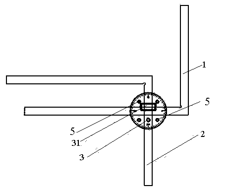
[0047] Such as Figure 1 to Figure 15 As shown, the measuring combination tool for prefabricated installation of the measuring pipeline of this patent includes a first straight ruler or a right angle ruler 1, a second straight ruler or a right angle ruler 2, an upper rotating body, and a lower rotating body.
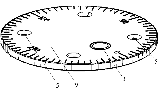
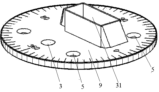
[0048] Among them, the upper rotating body includes an upper gland, an upper rotating disk 10, a rotating table 6, and four upper fixing bolts; wherein, the upper gland is a circular metal block with upper positioning holes 3 and four upper fixing circular holes 5 The upper rotating disk 10 is a circular metal block, the upper surface of the upper rotating disk 10 is provided with a first through chute 11, 4 upper fixing bolt holes, and a lower positioning hole 4 corresponding to the upper positioning hole 3 at the center position of the upper surface of the upper rotating disk 10; The positioning hole 3 and the lower positioning hole 4 are bolt holes; the upper fixing bolt hole corresponds to the upper fixing round hole 5 of the upper gland, the upper positioning hole 3 is set at the corresponding position of the first through chute 11, and the upper positioning bolt 13 is set In the upper positioning hole 3 and the lower positioning hole 4; 4 upper fixing bolts pass through the upper fixing round hole 5 and the upper fixing bolt hole to tightly fix the upper gland and the upper rotating disk 10 together, so that the upper surface of the upper rotating disk 10 There is no gap contact with the lower surface of the upper gland; the upper positioning bolt 13 locates the relative position of the upper rotating body and the lower rotating body through the upper positioning hole 3 and the lower positioning hole 4.
[0049] The lower surface of the upper rotating disk 10 is provided with a rotating table 6 whose lower diameter is larger than the upper diameter; the height of the rotating table 6 is consistent with the thickness of the lower sliding disk 16. The rotating table 6 set on the upper rotating disc 10 is a stepped structure, the upper part is a cylinder, and the lower part is a round table with a larger diameter than the cylinder; the circular hole of the lower sliding disc 16 is a stepped round hole, and the diameter of the upper part of the circular hole corresponds to The diameter of the lower part of the platform 6 corresponds to each other, and the diameter of the lower part of the circular hole corresponds to the diameter of the lower part of the rotating platform 6, and both are tightly fitted.
[0050] The lower rotating body includes a lower gland 15, a lower sliding plate 16, a lower fixing bolt, and a lower positioning bolt 25.
[0051] Among them, the lower sliding plate 16 is a split circular metal block composed of two symmetrical semicircular metal blocks, and the center is provided with a circular limiting hole 24 whose lower diameter is larger than the upper diameter; the upper diameter of the circular limiting hole 24 and the rotation The upper diameters of the table 6 correspond to each other so that the rotating table 6 is tightly fitted with the circular limiting hole 24, and the lower diameter of the circular limiting hole 24 is opposite to the lower diameter of the rotating table 6; the two semicircular metal blocks are respectively Set two lower sliding plate fixing bolt holes 19. The matching tolerance of the rotating table 6 and the circular limiting hole 24 is 0.02mm.
[0052] The lower gland 15 is a circular metal block. The left and right sides of the lower gland 15 are respectively provided with two lower gland round holes 20 corresponding to the lower sliding plate fixing bolt holes 19; the center of the lower gland 15 has a lower positioning bolt Hole 21, the lower positioning bolt 25 is set in the lower positioning bolt hole 21, and the thread length of the lower positioning bolt 25 is greater than the depth of the lower positioning bolt hole 21 by 3-10mm; the upper surface center of the lower gland 15 is provided with a passage through the lower gland 15 second through chute 22 at the center of the circle; the lower fixing bolt passes through the fixing bolt hole of the lower sliding disc 16 and the lower gland round hole 20 to tightly fix the lower gland 15, the lower sliding disc 16 together, so that the lower sliding disc 16 The lower surface is in seamless contact with the upper surface of the lower gland 15. The center of the upper surface of the lower gland 15 is also provided with a third through chute, the third through chute and the second through chute 22 cross; the depth of the third through chute is twice the depth of the second through chute 22 .
[0053] The first straight ruler or the square ruler 1 is arranged in the first through chute 11 or the second through chute 22.
[0054] The second ruler or square ruler 2 is arranged in the second through chute 22.
[0055] If necessary, an angle value is engraved on the upper surface of the upper gland and the circumferential direction, and an angle value is engraved on the circumferential direction of the upper rotating disk 10.
[0056] The depth of the first through chute 11 of the rotating disk is greater than the thickness of the first straight ruler or the square ruler 1, the second ruler or the square ruler 2, the third ruler or the square ruler. The depth of the second through chute 22 of the lower gland 15 is greater than the thickness of the first straight ruler or the square ruler 1, the second ruler or the square ruler 2, the third ruler or the square ruler.
[0057] The upper rotating body and the lower rotating body have the same diameter. Threads are provided in various bolt holes. A thread can be provided in the round hole.

PUM

no PUM

Description & Claims & Application Information

We can also present the details of the Description, Claims and Application information to help users get a comprehensive understanding of the technical details of the patent, such as background art, summary of invention, brief description of drawings, description of embodiments, and other original content. On the other hand, users can also determine the specific scope of protection of the technology through the list of claims; as well as understand the changes in the life cycle of the technology with the presentation of the patent timeline. Login to view more.

Similar technology patents

Control circuit and method for a buck-boost power converter

ActiveUS20110074373A1improve efficiencyminimize output ripple
Owner:RICHTEK TECH

Classification and recommendation of technical efficacy words

  • Improve efficiency
  • High precision

Method for forecasting short-term power in wind power station

InactiveCN102102626AHigh precision
Owner:NORTH CHINA ELECTRIC POWER UNIV (BAODING) +1

Numerical control machine tool wear monitoring method

InactiveCN102091972AHigh precisionReal-time monitoring of tool wear
Owner:HUAZHONG UNIV OF SCI & TECH +1

Advertisement recommendation method and apparatus

ActiveCN104965890AHigh precisionPrecise screening
Owner:SHENZHEN TENCENT COMP SYST CO LTD
Why Eureka
Try Eureka