Hydraulic-drive amphibious boat

An amphibious and hydraulic technology, applied in amphibious vehicles, motor vehicles, transportation and packaging, etc., can solve the problems of small driving torque, increased ship failure rate, increased hull weight, etc. Effects of improving maneuverability and increasing endurance

Active Publication Date: 2014-06-18
QINGDAO TECHNOLOGICAL UNIVERSITY
View PDF6 Cites 19 Cited by
  • Summary
  • Abstract
  • Description
  • Claims
  • Application Information

AI Technical Summary

Problems solved by technology

[0003] The current land drive of amphibious ships is mainly driven by hub motors, which have strict sealing requirements, are not safe, and have low drive torque.
Many amphibious boats are driven separately on land and in water. When on land, the steering wheel is used to control the direction, while in the water, you need to sit at the stern and manually control the outboard motor, which is time-consuming and laborious, and the steering of the outboard motor Can't get precise control
[0004] The wheels of existing amphibious electric boats cannot be retracted upwards, and it is easy to catch other things in the water, get entangled in the car, and affect the driving performance of the boat
[0005] Each wheel of the amphibious boat developed by sealegs is driven by a hydraulic motor. This driving method undoubtedly increases the weight of the hull and makes the price very expensive
This ship uses a gasoline...

Method used


Image

  • Hydraulic-drive amphibious boat
  • Hydraulic-drive amphibious boat
  • Hydraulic-drive amphibious boat

Examples


Embodiment Construction

[0068] The present invention will be further described below in conjunction with the accompanying drawings and embodiments.

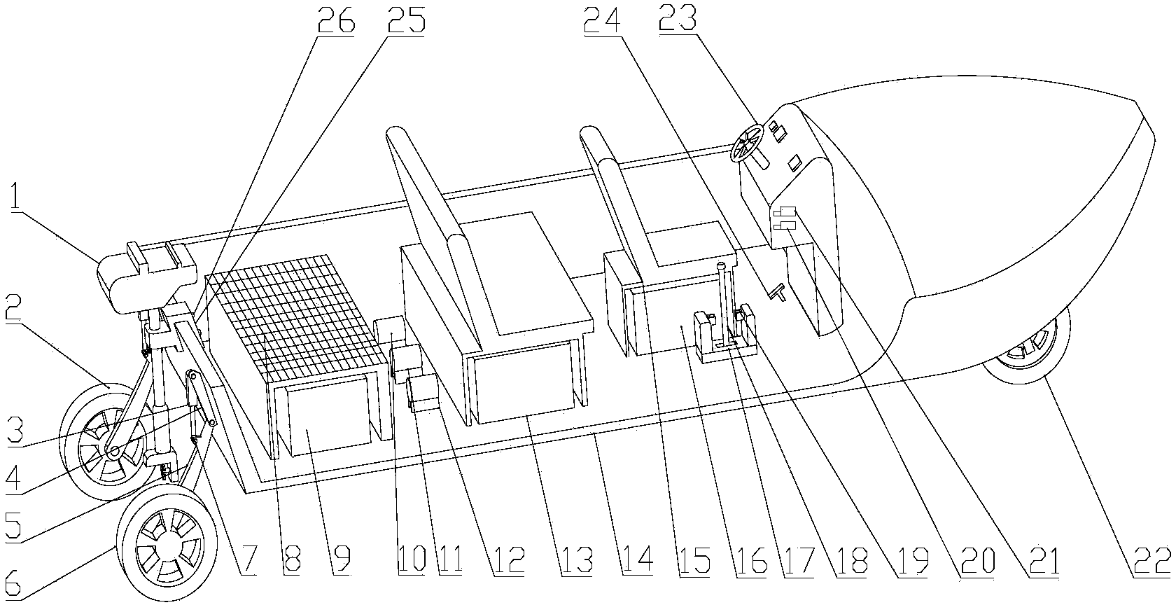
[0069] figure 1 This is the overall structure diagram of the amphibious ship (the starboard side is omitted for the convenience of observing), which shows the various components of the amphibious ship. Depend on figure 1 It can be known that the ship's water drive is driven by the outboard motor 1, the steering wheel 23 can control its direction, and the Hall type electronic accelerator pedal 24 can control the speed of the outboard motor 1 with a magnetic signal to the master controller 167. The outboard motor 1 is fixed on the hull 14 through a fixed tightening seat 25 and a fixed clamping bolt 26 .

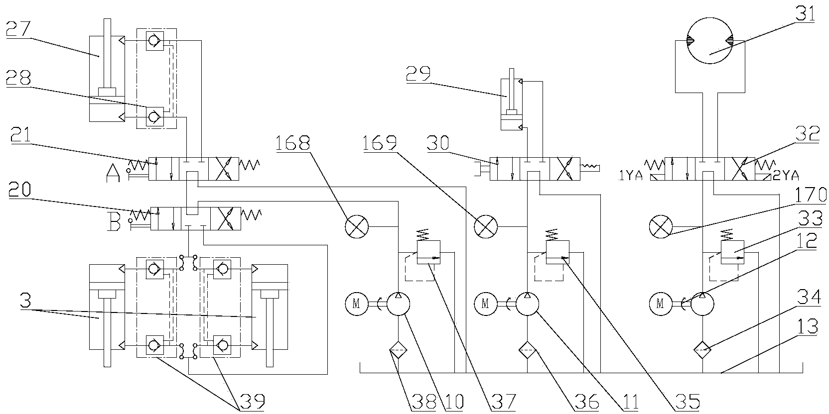
[0070] When walking on land, the hydraulic outrigger motor pump 10 starts, the conversion box lever 18 converts the transmission mode, and the front wheel manual reversing valve 21 and the rear wheel manual reversing valve 20 control the front outrigge...


PUM

PropertyMeasurementUnit
Thicknessaaaaaaaaaa

Abstract

The invention relates to a hydraulic-drive amphibious boat. According to the hydraulic-drive amphibious boat, traveling in the double environments including the waterway environment and the landway environment is achieved. The hydraulic-drive amphibious boat comprises a hull, wherein an outboard engine is installed on the tail portion of the hull and is connected with a control circuit; a land traveling wheel system is installed at the bottom of the hull, each wheel in the land traveling wheel system is provided with a hydraulic motor, and the hydraulic motors are connected with a hydraulic control device; a hydraulic steering device is further arranged on the front wheels, and is also connected with the hydraulic control device; each wheel in the land traveling wheel system is provided with a hydraulic lifting device, and the hydraulic lifting devices are connected with the hydraulic control device; the hydraulic control device is connected with a water and land mode switching box, and the water and land mode switching box comprises a first output shaft and a second output shaft; the first output shaft is connected with the hydraulic control device through a rotary valve; the second output shaft is connected with the outboard engine through a transmission device; a switching device is connected with a switching box lever; a steering wheel device is connected with an input shaft of the switching device; the hydraulic control device is provided with a plurality of motor pumps which are connected with the control circuit; a power source provides needed electric power.

Description

Technical field: [0001] The invention relates to a hydraulically driven amphibious ship. Background technique: [0002] Speedboat is a common means of water transportation, but it needs a trailer to transfer on land. Especially in the places where there are many shallows, how to transfer the motorboat to the deep water becomes a difficult problem. [0003] The current land drive of amphibious ships is mainly driven by hub motors, which have strict sealing requirements, are not safe, and have low drive torque. Many amphibious boats have separate land and water drive modes. When on land, the steering wheel is used to control the direction, while in the water, you need to sit at the stern and manually control the outboard motor, which is time-consuming and laborious, and the steering of the outboard motor cannot be precisely controlled. [0004] The wheels of the existing amphibious electric boats cannot be retracted upwards, and it is very easy to hang other things in the w...

Claims


Application Information

Patent Timeline
IPC IPC(8): B60F3/00
Inventor 王磊李长河
Owner QINGDAO TECHNOLOGICAL UNIVERSITY
Why Eureka
Try Eureka