
Three-degree-of-freedom space simulator

A technology of simulators and degrees of freedom, applied in the field of aerospace, can solve the problems of space simulation test equipment such as poor versatility, high maintenance costs, and complex mechanical structures, and achieve the effects of light weight, convenient maintenance, and high strength

Active Publication Date: 2014-06-18
HARBIN INST OF TECH
View PDF5 Cites 21 Cited by
  • Summary
  • Abstract
  • Description
  • Claims
  • Application Information

AI Technical Summary

Problems solved by technology

[0006] The purpose of the present invention is to solve the problems of poor versatility, high cost, complicated mechanical structure and high maintenance cost of space simulation test equipment. The present invention provides a three-degree-of-freedom space simulator

Method used


Image

  • Three-degree-of-freedom space simulator
  • Three-degree-of-freedom space simulator
  • Three-degree-of-freedom space simulator

Examples


specific Embodiment approach 1

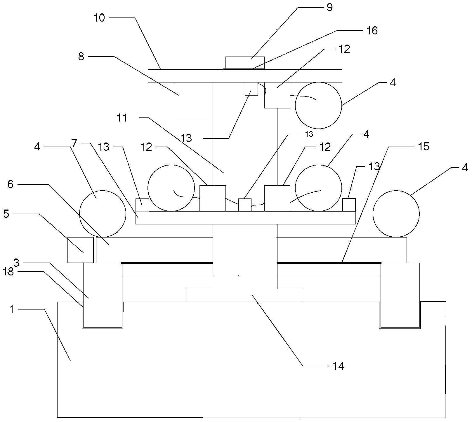
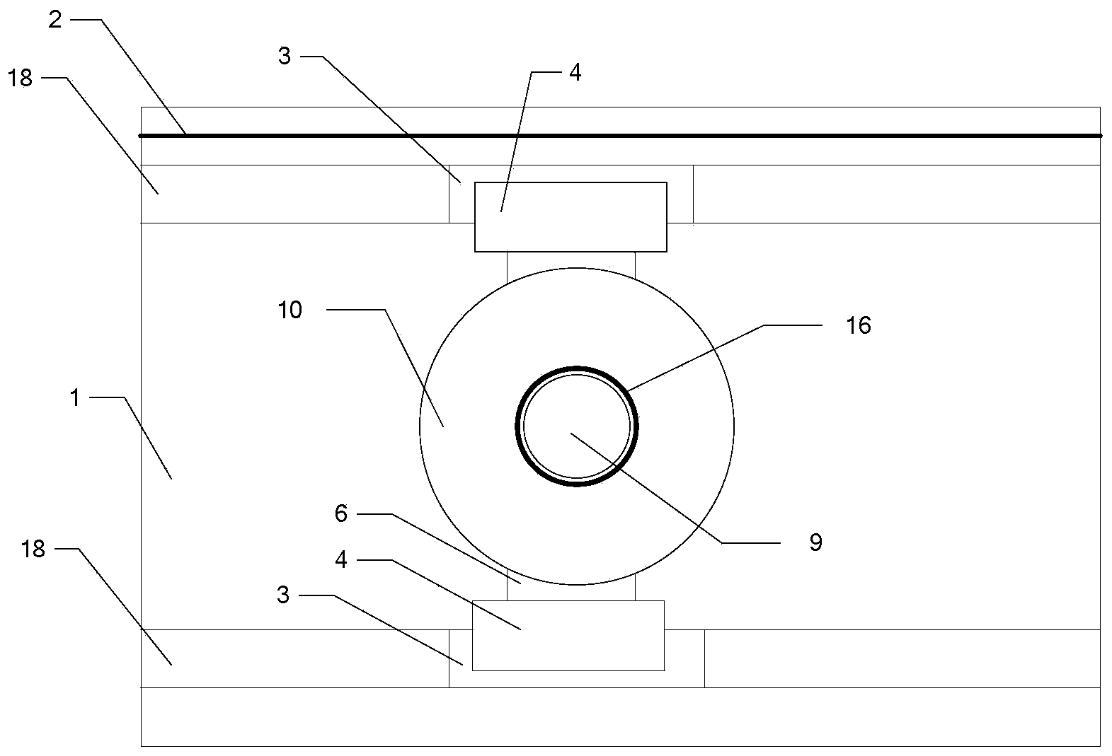
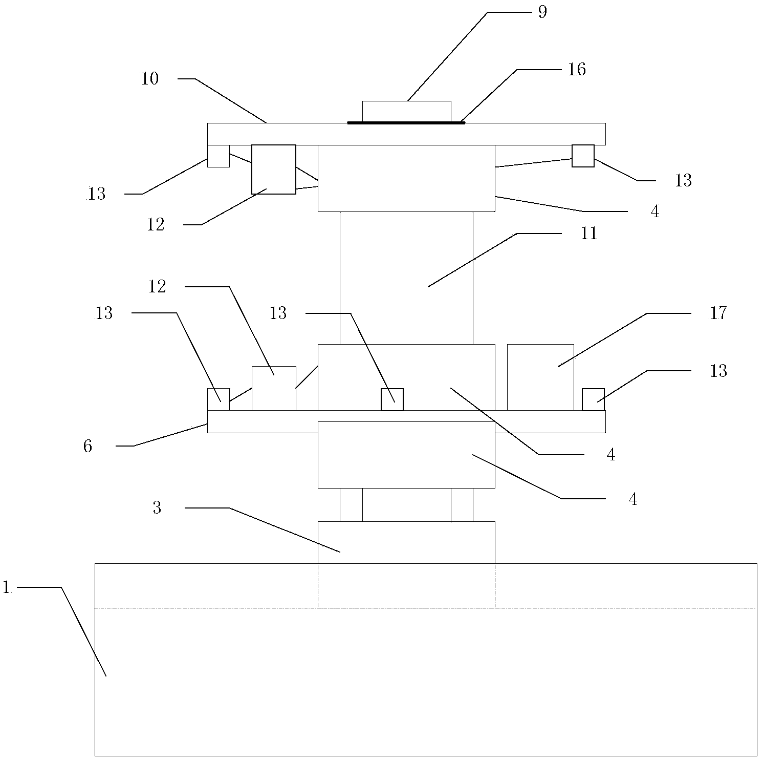
[0034] Specific implementation mode one: combine figure 1 , figure 2 and image 3 Describe this embodiment, the three-degree-of-freedom space simulator described in this embodiment includes a base 1, an X-axis grating ruler 2, an air bearing guide rail 3, five high-pressure gas cylinders 4, an X-axis communication control module 5, a gas Floating beam 6, lower plate 7, rotary shaft communication control module 8, reaction flywheel 9, upper plate 10, rotary shaft 11, 3 pressure regulating valves 12, 6 nozzles with solenoid valves 13, air bearing sleeve 14, Y axis grating ruler 15, circular grating ruler 16 and Y-axis communication control module 17;

[0035] The top surface of the base 1 is provided with two parallel air flotation grooves 18, the air flotation beam 6 is arranged on the base 1, and the bottoms of the two ends of the air flotation beam 6 are respectively fixed with air flotation guide rails 3, and the two air flotation beams The floating guide rails 3 are res...

specific Embodiment approach 2

[0049] Embodiment 2: This embodiment is a further limitation of the three-degree-of-freedom space simulator described in Embodiment 1. The bottom of the air bearing guide rail 3 is provided with 2×6 air bearing holes with a diameter of 0.15mm. The bottom plate of the cover 14 is provided with 4×6 air flotation holes with a diameter of 0.15mm.

specific Embodiment approach 3

[0050] Embodiment 3: This embodiment is a further limitation of the three-degree-of-freedom space simulator described in Embodiment 1, and the nozzle 13 is a Laval nozzle.


PUM


Abstract

The invention discloses a three-degree-of-freedom space simulator and belongs to the field of simulating equipment in the aerospace field. The three-degree-of-freedom space simulator aims to solve the problem that space simulated test equipment is poor in universality, high in cost, complicated in mechanical structure and high in maintenance cost. The three-degree-of-freedom space simulator comprises a two-degree-of-freedom horizontally-moving part and a single-degree-of-freedom rotating part, a high-pressure gas cylinder is adopted by the supporting surface of the simulator, the supporting surface of the simulator is designed according to the air flotation principle, the horizontal movement in the horizontal XY direction of the two-degree-of-freedom horizontally-moving part is achieved through an air floating guide rail, an air floating groove, an X-axis grating ruler and a Y-axis grating ruler, and 360-degree movement in the clockwise direction and in the anticlockwise direction of the single-degree-of-freedom rotating part is achieved through a rotary shaft, a reaction flywheel and a round grating ruler. The simulator further comprises three communication controllers, wherein the three communication controller are used for acquiring the location information in the X-axis direction, the location information in the Y-axis direction, and the location information in the rotation-axis direction respectively and driving nozzles of the simulator to spray air. The three-degree-of-freedom space simulator is used for aerospace tests for simulating the micro-gravity and micro-interference environment of the outer space.

Description

technical field [0001] The invention relates to a simulation device in the aerospace field, in particular to an experimental environment device used in aerospace equipment to simulate microgravity. Background technique [0002] Before the launch of a spacecraft, ground simulation tests are required, and the test device for simulating the outer space environment plays an important role in the development of aerospace technology. [0003] The core of the realization process of the full physical simulation of the space simulator is to minimize the external disturbance on the ground and simulate its attitude movement in the weightless state. The space simulator relies on its own high-pressure gas cylinder to form an air film between the marble base and the air flotation guide rail, the marble base and the air flotation sleeve, the rotating shaft and the upper plate, and generate an upward uniform force to offset the influence of gravity. Therefore, the movement of the three dir...

Claims


Application Information

Patent Timeline
IPC IPC(8): B64G7/00
Inventor 刘杨刘启循付振宪陈兴林周乃新李浩然董岳陈震宇王伟峰
Owner HARBIN INST OF TECH
Learn More