

Dry mortar packing machine
A dry powder mortar and packaging machine technology, applied in the directions of packaging, transportation and packaging, packaging item types, etc., can solve the problems of low packaging efficiency and low discharging efficiency, and achieve high packaging efficiency, high discharging efficiency, packaging and weighing. accurate effect
- Summary
- Abstract
- Description
- Claims
- Application Information
AI Technical Summary
Problems solved by technology
Method used
Image

Examples
Embodiment Construction
[0022] The present invention will be further described below in conjunction with accompanying drawing and specific embodiment:
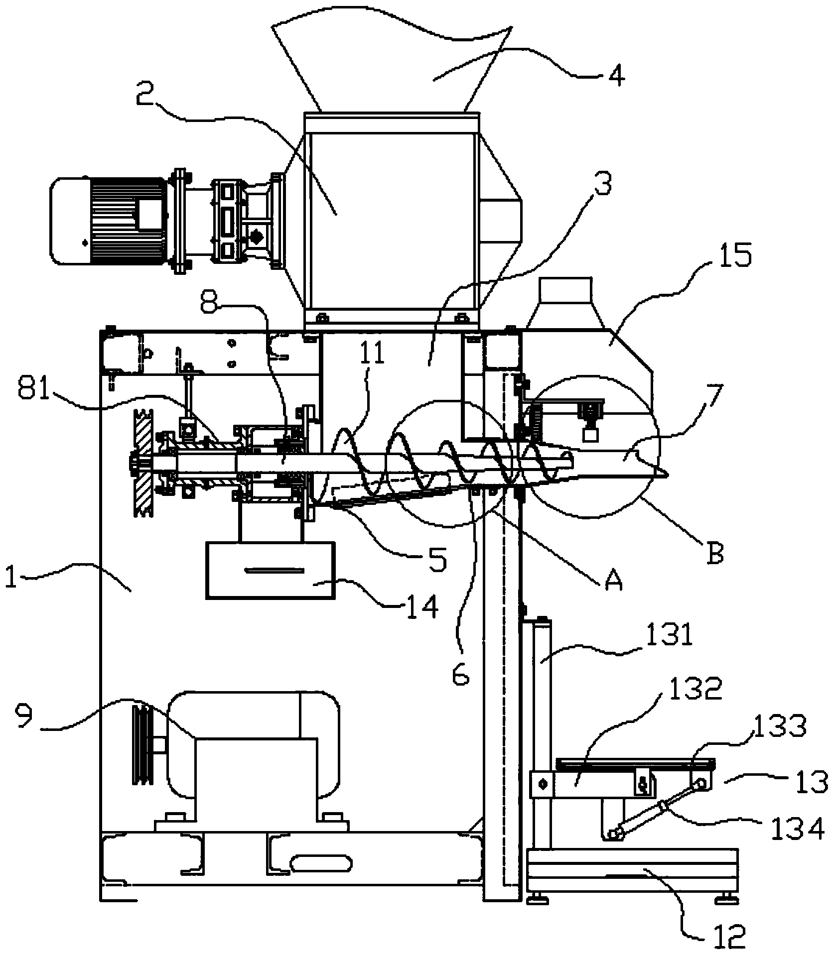
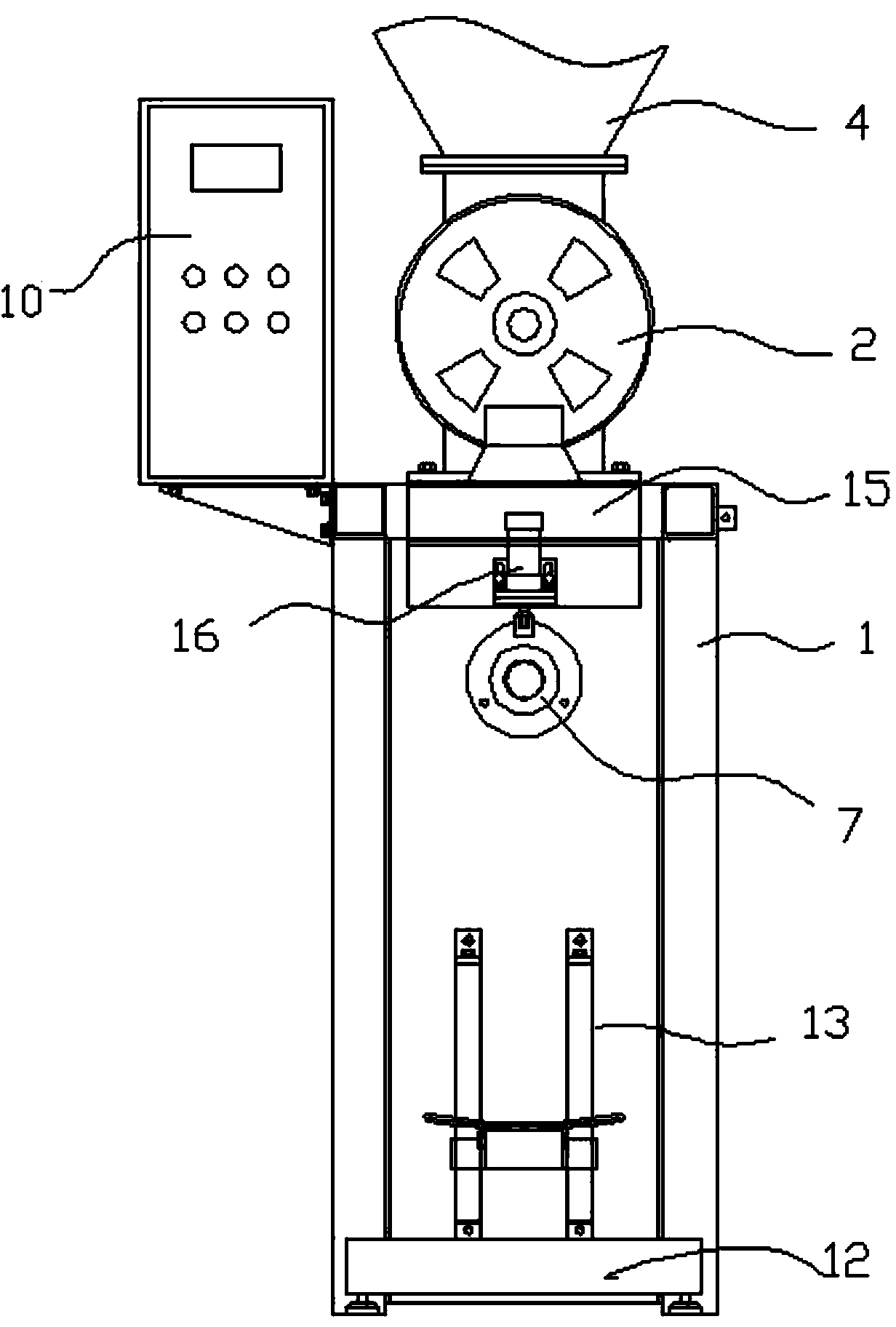
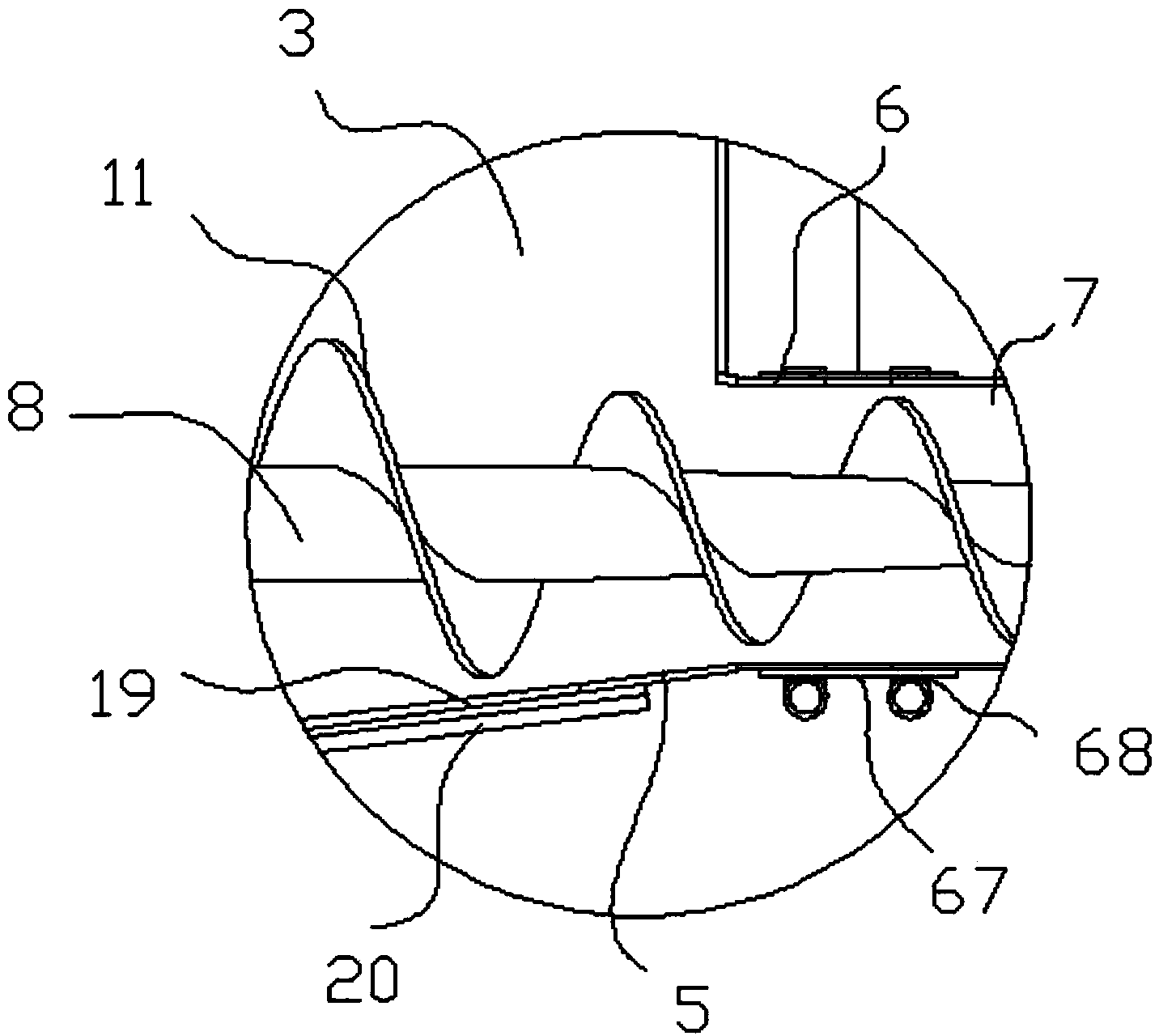
[0023] Such as figure 1 A kind of dry powder mortar packing machine shown, comprises frame 1, blower fan 2, is provided with vertical feed passage 3 in the frame, the upper end of feed passage is connected with the outlet of blower fan, the upper end of blower fan is connected with material The warehouse 4 is connected, the lower end of the feeding channel 3 is provided with a closed baffle 5, the side of the lower end of the feeding channel is provided with a discharge pipe 6, the outer end of the discharge pipe is provided with a discharge nozzle 7, and the lower end of the feeding channel is provided with a horizontal Rotating shaft 8, the left end of rotating shaft stretches out of feeding channel and is connected with rotating shaft fixed seat 81, the right end of rotating shaft stretches in the discharge pipe and is coaxially distributed with t...
PUM
 Abstract
Description
Claims
Application Information