Supercharge Your Innovation With Domain-Expert AI Agents!

Pneumatic pusher dog conveying roller machine

A conveying roller and pneumatic technology, applied in the field of pneumatic claw conveying roller bed, can solve the problems of high labor intensity and low work efficiency of operators, and achieve the effects of reduced operator intensity, high work efficiency and high conveying efficiency.

Inactive Publication Date: 2014-06-18
黄兴来
View PDF0 Cites 2 Cited by
  • Summary
  • Abstract
  • Description
  • Claims
  • Application Information

AI Technical Summary

Problems solved by technology

[0003] The purpose of the present invention is to solve the problems of high labor intensity and low work efficiency of operators existing in the existing locomotive bearing inner diameter measuring machine for conveying the slide plate, and to provide a pneumatic claw conveying roller bed

Method used


Image

  • Pneumatic pusher dog conveying roller machine
  • Pneumatic pusher dog conveying roller machine

Examples


Embodiment Construction

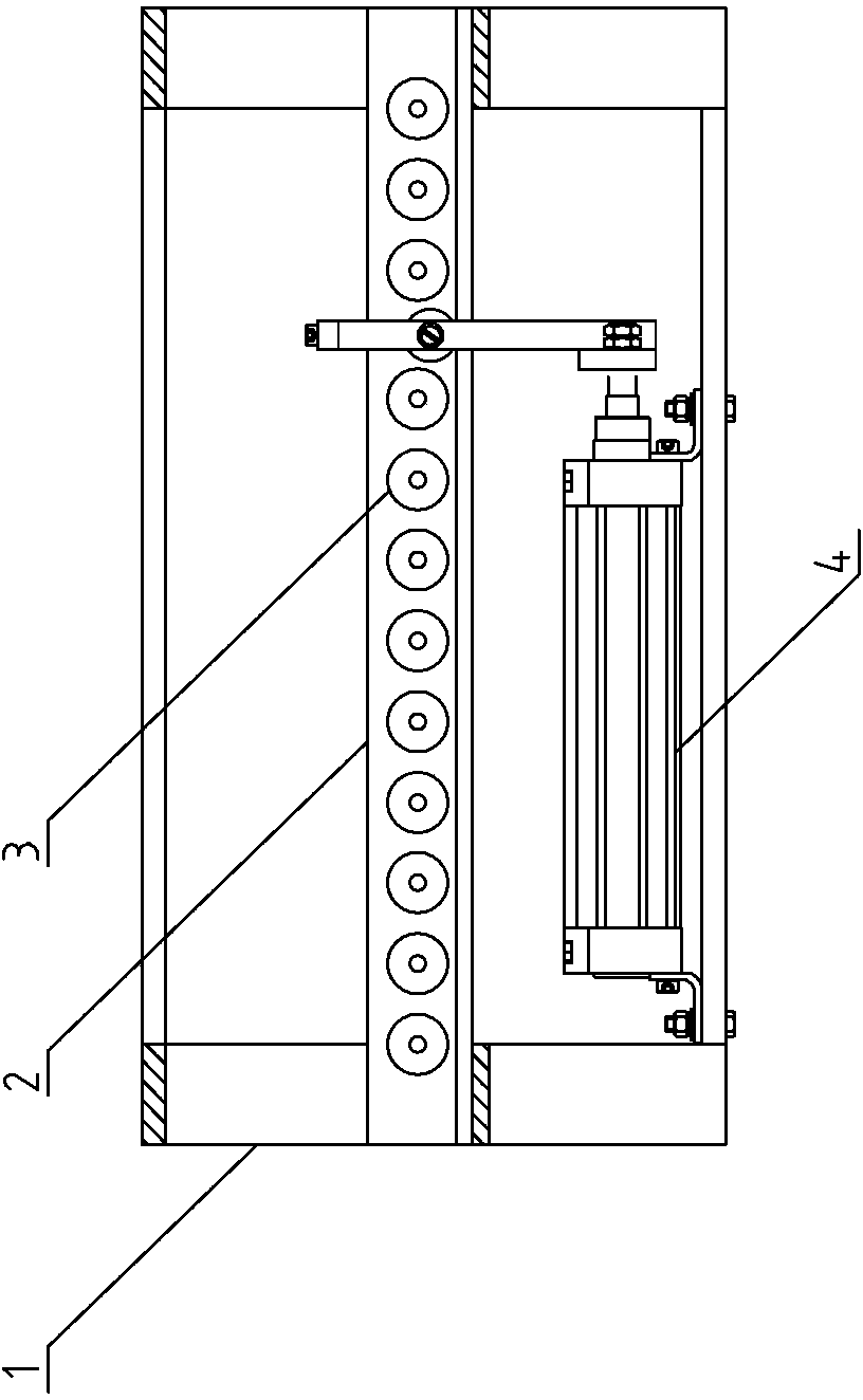
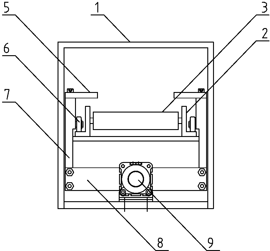
[0009] see figure 1 : a pneumatic claw conveying roller bed, which is provided with a frame 1; especially: a rib track 2 is installed in the frame 1, and a roller 3 is installed on the rib track 2; the frame 1 is located at the rib track 2 The claw mechanism 4 is installed below; the claw mechanism 4 is composed of a one-way claw 5, a guide roller 6, a lever 7, a connecting plate 8 and a cylinder 9 (see figure 2 ), the cylinder 9 is installed on the bottom plate of the frame 1, the middle part of the connecting plate 8 is connected with the end of the piston rod of the cylinder 9, the two driving rods 7 are respectively installed on the two ends of the connecting plate 8, and the two guide rollers 6 is respectively installed on the inner side of the two driving rods 7, and the two one-way driving claws 5 are respectively installed above the two driving rods 7; the two driving rods 7 in the claw mechanism 4 are respectively installed on the On both sides of the sidewall track...


PUM


Abstract

The invention relates to an improvement in a railway locomotive bearing internal diameter measurer conveying sliding plate, and discloses a pneumatic pusher dog conveying roller machine, which is provided with a rack. The pneumatic pusher dog conveying roller machine is characterized in that a flange rail and a pusher dog mechanism are arranged in the rack, wherein rollers are arranged on the flange rail; the pusher dog mechanism consists of two one-way pusher dogs, two guide rollers, two stirring rods, a connecting plate and a cylinder; the cylinder is arranged on a bottom plate of the rack; the middle part of the connecting plate is connected with the end part of a piston rod of the cylinder; the two stirring rods are arranged at the two ends of the connecting plate respectively; the two guide rollers are arranged on the inner sides of the two stirring rods respectively; the two one-way pusher dogs are arranged above the two stirring rods respectively. According to the pneumatic pusher dog conveying roller machine, the problems of high labor intensity of an operator and low working efficiency of a conventional locomotive bearing internal diameter measurer conveying sliding plate are solved; the pneumatic pusher dog conveying roller machine is mainly used as the improvement in the conventional locomotive bearing internal diameter measurer conveying sliding plate.

Description

technical field [0001] The invention relates to the improvement of a conveying slide plate of a railway locomotive bearing inner diameter measuring machine, which is a pneumatic claw conveying roller bed. Background technique [0002] The locomotive bearing inner diameter measuring machine is equipped with a conveying slide plate, which is used to convey the bearing to the bottom of the measuring machine’s measuring head; in the prior art, the conveying slide plate of the locomotive bearing inner diameter measuring machine is a groove-shaped plate structure, and the bearing to be tested is operated on the groove-shaped plate. The personnel are pushed to the bottom of the measuring head of the measuring machine to carry out the measuring operation; the problems existing in the conveying skateboard of the locomotive bearing inner diameter measuring machine in the prior art are: the labor intensity and low work efficiency of the operator of the skateboard conveying the bearing. ...

Claims


Application Information

Patent Timeline
Patent Type & Authority Applications(China)
IPC IPC(8): B65G47/82B65G13/00
Inventor 黄兴来
Owner 黄兴来
Features
  • R&D
  • Intellectual Property
  • Life Sciences
  • Materials
  • Tech Scout
  • Unparalleled Data Quality
  • Higher Quality Content
  • 60% Fewer Hallucinations
Learn More