Cooling device of pavement cutting machine

A technology of cooling device and cutting machine, applied in the direction of road, road, road repair, etc., can solve the problems such as the inability to cool down the cutting piece, the inability to cool down, and the small contact area, so as to improve the cooling effect, reduce frictional heat generation, reduce The effect of water consumption

Inactive Publication Date: 2014-06-18
王威
View PDF8 Cites 2 Cited by
  • Summary
  • Abstract
  • Description
  • Claims
  • Application Information

AI Technical Summary

Problems solved by technology

[0003] First, when the cutting machine is running, the cutting piece rotates clockwise at high speed to cut the road surface, the contact part of the cutting piece and the road surface rubs violently to generate heat, and then rotates away from the road surface, so the temperature at the rear of the cutting piece is obviously higher than that at the front If the temperature of the front of the cutting disc is sprayed to cool down, the temperature at the rear of the cutting disc with a higher temperature cannot be effectively reduced, and the purpose of cooling the cutting disc cannot be achieved;
[0004] Second, the water of the existing road cutting machine is sprayed onto the cutting piece in the form of a single stream of water, and the contact area with the cutting piece is small, and because the water spraying direction is fixed, there is a blind area for spraying water on the cutting piece, making the cutting The uneven temperature on the chip seriously affects the service life of the cutting chip;
[0005] Third, the existing pavement cutting machine cannot spray water on the rotating shaft and the cutting piece of the cutting machine to cool down at the same time, which affects the use of the rotating shaft of the cutting machine;
[0006] Fourth, the heat generated when the cutting disc cuts the road surface mainly comes from the part where the cutting disc contacts the road surface, and the existing road cutting machine cannot cool down this part

Method used


Image

  • Cooling device of pavement cutting machine
  • Cooling device of pavement cutting machine
  • Cooling device of pavement cutting machine

Examples


Embodiment 1

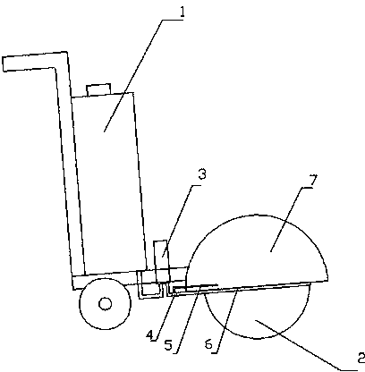
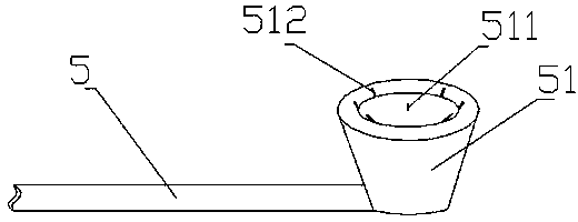
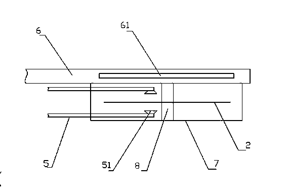
[0024] Embodiment 1: as figure 1 , figure 2 with image 3 As shown, a cooling device for a road cutting machine includes a water tank 1, a booster pump 3 and a water spray device arranged on the cutting machine. The water spray device includes a water spray pipe I5 and a water spray pipe II6. The water outlet of the water tank 1 is connected to the The water inlet pipe of the booster pump 3 is connected, and the water outlet pipe of the booster pump 3 is connected to the water spray pipe I5 in the mask 7 of the cutting piece 2 and the water spray pipe II6 arranged on the outside of the mask 7 through the tee 4 respectively. Two nozzles 51 respectively located on both sides of the cutting piece 2 are arranged on the pipe I5, and a plurality of water spray holes are arranged on the nozzle 51. The water spray holes are divided into a central water spray hole 511 and an edge water spray hole 512. Set in the central position of the nozzle 51, the water flow is sprayed perpendicu...

Embodiment 2

[0025] Example 2: as figure 1 , figure 2 with Figure 4 As shown, a cooling device for a road cutting machine includes a water tank 1, a booster pump 3 and a water spray device arranged on the cutting machine. The water spray device includes a water spray pipe I5 and a water spray pipe II6. The water outlet of the water tank 1 is connected to the The water inlet pipe of the booster pump 3 is connected, and the water outlet pipe of the booster pump 3 is connected to the water spray pipe I5 in the mask 7 of the cutting piece 2 and the water spray pipe II6 arranged on the outside of the mask 7 through the tee 4 respectively. Two nozzles 51 respectively located on both sides of the cutting piece 2 are arranged on the pipe I5, and a plurality of water spray holes are arranged on the nozzle 51. The water spray holes are divided into a central water spray hole 511 and an edge water spray hole 512. Set in the central position of the nozzle 51, the water flow is sprayed perpendicula...


PUM


Abstract

The invention relates to a cooling device of a pavement cutting machine. The cooling device of the pavement cutting machine comprises a water tank on the cutting machine, a water outlet of the water tank is connected with a water inlet pipe of a booster pump, a water outlet pipe of the booster pump is respectively connected with a water spraying pipe I going into a mask of a cutting disc and a water spraying pipe II at the outer side of the mask by virtue of a three-way pipe, sprayers at the two sides of the cutting disc are respectively arranged on the water spraying pipe I, multiple water spraying holes are formed in each sprayer and comprise center water spraying holes and edge water spraying holes, water flowing out of each center water spraying hole is vertical to the corresponding sprayer, water flowing out of each edge water spraying hole is sprayed out toward the outer side of the corresponding sprayer in an inclined way, one part of water can be sprayed onto a rotating shaft of the cutting machine, and water in the water spraying pipe II is sprayed out in a water curtain shape and acts on a contact part between the cutting disc and a pavement, so that heat produced by friction is reduced. By the cooling device of the pavement cutting machine, the temperature of the cutting disc can be effectively reduced while the rotating shaft of the cutting machine can be cooled, and heat produced by friction between the cutting disc and the pavement can be reduced when the pavement is cut by the cutting disc.

Description

technical field [0001] The invention relates to a road maintenance equipment, in particular to a cooling device for a road cutting machine. Background technique [0002] The road cutting machine is a commonly used equipment in road maintenance engineering, mainly used for cutting and repairing the road surface. Due to the high strength of the concrete pavement, the friction between the cutting blade and the road surface will generate a lot of heat during the cutting process, which makes the temperature of the cutting blade on the cutting machine and the rotating shaft of the cutting machine higher. If the temperature is not cooled in time, it will greatly affect the cutting of the cutting machine. Efficiency and service life of cutting disc and shaft. In the existing pavement cutting machines, water cooling is generally adopted, and the water in the water tank is directly sprayed on the front or rear of the cutting blade through the conduit, but the cooling effect of this m...

Claims


Application Information

Patent Timeline
Patent Type & Authority Applications(China)
IPC IPC(8): E01C23/09
Inventor 王威
Owner 王威
Why Eureka
Try Eureka