Corrugated steel web combination ribbed beam and construction process thereof

A corrugated steel web and rib beam technology, applied in bridges, bridge construction, bridge materials, etc., can solve problems such as construction difficulties, high input costs, and difficulties in concrete pouring and prestressed positioning.

Inactive Publication Date: 2014-06-18
HUNAN UNIV +2
View PDF8 Cites 4 Cited by
  • Summary
  • Abstract
  • Description
  • Claims
  • Application Information

AI Technical Summary

Problems solved by technology

However, in practical engineering applications, prefabricated concrete rib beam members have a relatively large self-weight, which requires corresponding transportation and lifting equipment for transportation and installation, which brings many difficulties to the construction
In addition, in the practical application of rib bridges, due to the thin concrete web (generally 18cm to 20cm thick), concrete pouring and prestress positioning are very difficult, so there are also many quality problems, such as web cracking, bottom slab cracking etc.
At the same time, because the thickness of the concrete web in the rib girder bridge is relatively thin, the prestress of the rib girder bridge must be tensioned at the beam end, the tension space is limited, and the prestressed tendons must also be arranged throughout the entire span. , this will lead to waste of prestressed materials, not only that,

Method used


Image

  • Corrugated steel web combination ribbed beam and construction process thereof
  • Corrugated steel web combination ribbed beam and construction process thereof
  • Corrugated steel web combination ribbed beam and construction process thereof

Examples


Embodiment 1

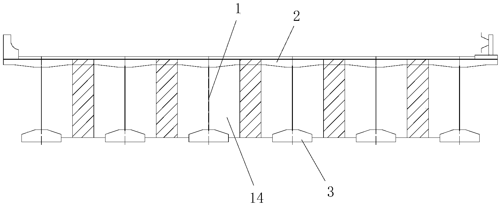
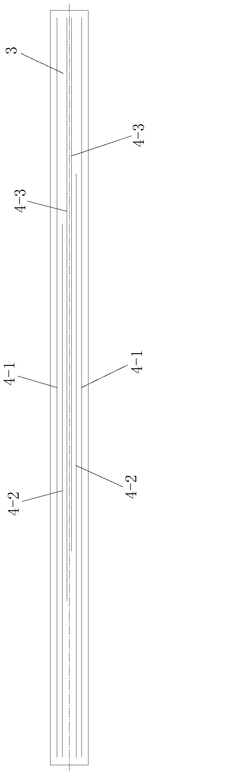
[0078] Such as figure 1 A corrugated steel web composite rib beam shown includes a lower flange plate 3, an upper flange plate 2 located above the lower flange plate 3 and a support between the lower flange plate 3 and the upper flange plate 2 The corrugated steel web 1, the upper flange plate 2 and the lower flange plate 3 are arranged horizontally along the longitudinal bridge direction of the bridge to be constructed, and the lower flange plate 3 is a cast-in-place concrete plate and it is connected with the upper flange The plate 2 is fastened and connected as a whole by the corrugated steel web 1 , and the bottom of the corrugated steel web 1 and the lower flange plate 3 are fastened and connected by a lower shear connector. Such as figure 2 As shown, a prestressing system is arranged in the lower flange plate 3, and the prestressing system includes a middle prestressing structure arranged in the middle of the lower flange plate 3 and two side walls respectively arrange...

Embodiment 2

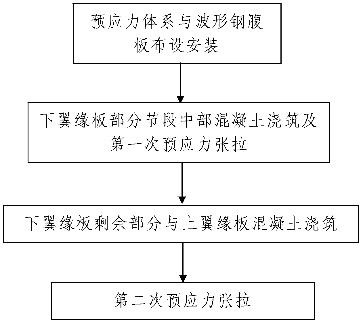
[0117] In this embodiment, the construction of corrugated steel web composite rib beam is different from that in Embodiment 1 in that: the middle prestressed structure is the second prestressed structure. to combine Figure 7 , the second prestressing structure includes a plurality of fourth prestressing tendons 4-4 and a plurality of fifth prestressing tendons 4-5, a plurality of fourth prestressing tendons 4-4 and a plurality of fifth prestressing tendons The prestressed tendons 4-5 are all arranged on the same horizontal plane. The lower flange plate 3 is formed by connecting a front end segment, a rear end segment and a middle segment connected between the front end segment and the rear end segment, the front end segment, the middle The segments and the rear end segments are arranged along the length direction of the lower flange plate 3 from front to rear. The length L1 of the middle section is 0.6L-0.7L, and the fourth prestressed tendons 4-4 and the fifth prestressed ...

Embodiment 3

[0140] In this example, if Figure 10 As shown, the difference between the corrugated steel web composite rib beam constructed and that in Embodiment 1 is that the lower shear connector is a second shear connector structure. The second shear connection structure includes a plurality of first transverse connectors passing through the lower part of the corrugated steel web 1, and the plurality of first transverse connectors are all located on the same horizontal plane and are all along the bottom flange plate 3. The width direction is arranged, and the multiple first transverse connectors are arranged along the length direction of the lower flange plate 3 from front to back. A first through hole through which the transverse connecting piece passes. The lower part of the corrugated steel web 1 and the multiple first transverse connectors are poured into the lower flange plate 3 . The first transverse connecting piece is a PBL connecting piece or a steel bar, and the PBL connect...


PUM


Abstract

The invention discloses a corrugated steel web combination ribbed beam and a construction process of the corrugated steel web combination ribbed beam. The corrugated steel web combination ribbed beam comprises bottom flange plates, top flange plates and corrugated steel webs, wherein the corrugated steel webs are arranged between the bottom flange plates and the top flange plates in a supporting mode. A prestress system is laid in each bottom flange plate and comprises a middle prestress structure and two side prestress structures. The construction process of the corrugated steel web combination ribbed beam comprises the following steps: firstly, the prestress systems and the corrugated steel webs are laid and installed; secondly, the bottom flange plates are constructed, wherein according to the step 201, concrete is poured into the middle of a segment of each bottom flange plate, and primary prestress tensioning is conducted; according to the step 202, the concrete is poured into the rest of each bottom flange plate, and secondary prestress tensioning is conducted; the top flange plates are constructed before the bottom flange plates are constructed or when the bottom flange plates are constructed or after construction of the bottom flange plates is completed. According to the corrugated steel web combination ribbed beam and the construction process of the corrugated steel web combination ribbed beam, the design is reasonable, construction is convenient, and the corrugated steel web combination ribbed beam which is constructed and formed is reasonable in stress, good in usage effect and capable of solving various problems of an existing concrete ribbed beam.

Description

technical field [0001] The invention belongs to the technical field of rib beam construction, and in particular relates to a corrugated steel web combined rib beam and a construction process thereof. Background technique [0002] Composite structure bridges properly combine two different materials, steel and concrete, to improve the stability, strength and efficiency of materials used in the structure. Among them, the corrugated steel web composite structure properly combines two different materials, steel and concrete, and the corrugated steel web is arranged between the upper and lower flange plates. Specifically, the corrugated steel web with a thickness of about 10mm to 20mm is used Instead of the traditional concrete web with a thickness of about 300mm to 800mm, the upper and lower flanges are both concrete slabs, and the corrugated steel web and concrete flange are combined to form an integral structure to bear the load together. The self-weight of the corrugated stee...

Claims


Application Information

Patent Timeline
IPC IPC(8): E01D2/02E01D21/00E01D101/28
Inventor 李立峰袁卓亚石雄伟侯嘉庆周聪柯亮亮许冰雷丹冯威田丞
Owner HUNAN UNIV
Why Eureka
Try Eureka